
Product Short Description
Product Overview
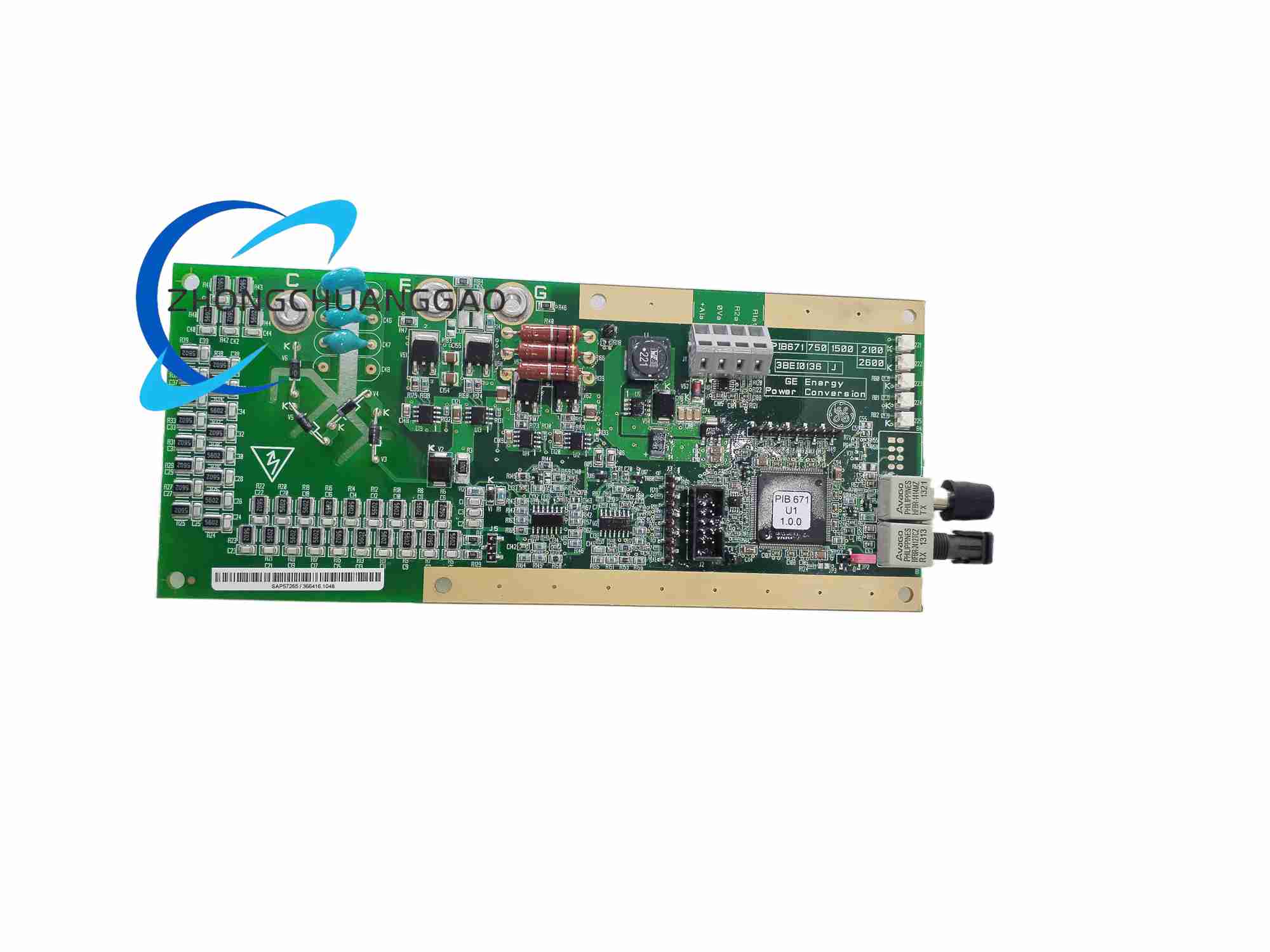
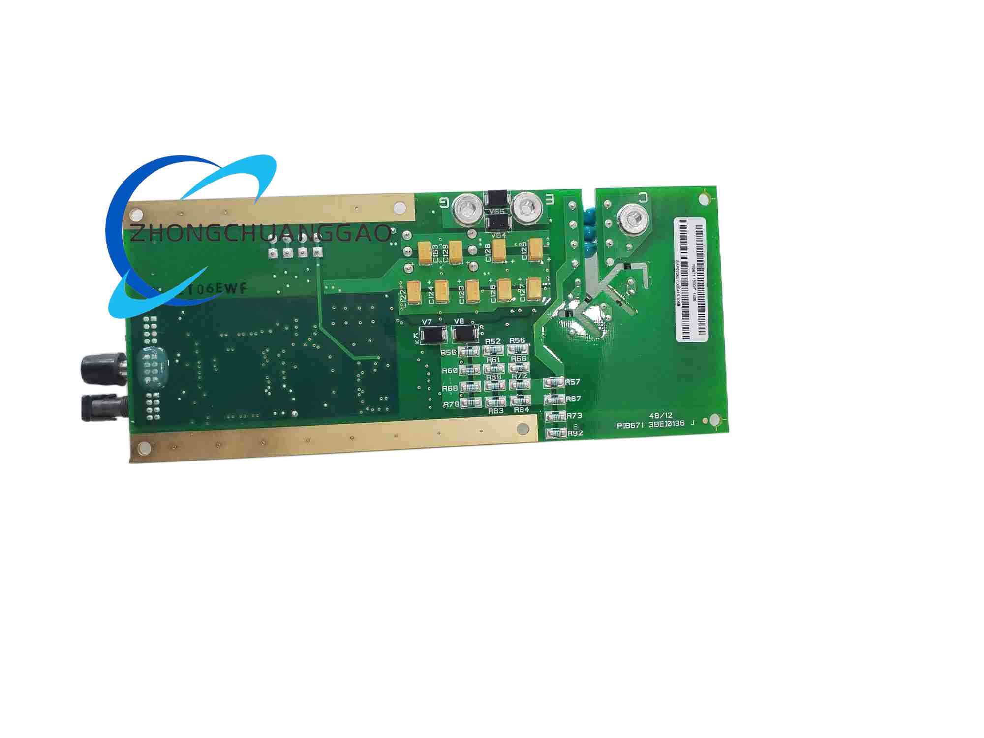
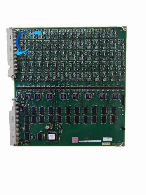
PIB671-1500 is a high-power industrial power interface core circuit board independently developed by Alstom (Converteam) for its ALSPA MV3000 medium voltage variable frequency drive series. The suffix 1500 represents the board’s rated continuous handling peak current capacity of 1500 Amperes, which undertakes the core signal conversion, gate drive protection and power stack monitoring tasks between the medium voltage drive main control CPU board and the high-power IGBT power module stack.
Description
Core Technical & Performance Specifications
- Power Current Handling Capacity
- Rated Continuous Supported IGBT Stack Current: 1500 A
- Instantaneous Overcurrent Fault Detection Threshold: 2250 A (1.5 times rated current)
- Maximum Allowable Burst Short-Circuit Current Tolerance: 5000 A instantaneous peak current, with microsecond-level rapid shutdown protection response
- Fiber Optic Gate Drive Communication Parameters
- Signal Transmission Medium: Plastic industrial multi-mode fiber optic cables
- Number of Independent Isolated Fiber Optic Transceiver Channels: 12 groups, corresponding to 6-phase medium voltage IGBT power bridge arm drive signals
- Signal Transmission Delay: Less than 200 ns one-way transmission latency, ensuring synchronous multi-bridge arm IGBT switching action
- Maximum Fiber Cable Transmission Distance: 20 m between PIB671-1500 board and each IGBT power module unit
- Electrical Working Power Parameters
- Auxiliary Control Power Supply Input Voltage: 220 VAC single-phase industrial auxiliary power supply
- Allowable AC Input Voltage Fluctuation Range: 187 VAC ~ 242 VAC (±15% nominal voltage)
- Rated Operating Power Consumption of the Board: 180 W under full-load IGBT drive signal output state
- Protection & Fault Response Performance
- IGBT Desaturation Fault Detection Response Time: Less than 2 μs from fault occurrence to gate drive signal shutdown output
- Junction Temperature Monitoring Sampling Cycle: 10 ms real-time continuous sampling of each IGBT module built-in temperature sensor signal
- Gate Drive Undervoltage/Overvoltage Fault Trigger Threshold: Undervoltage below 12 VDC, overvoltage above 18 VDC gate power supply voltage
- Environmental Working Parameters
- Continuous Operating Ambient Temperature Range: -10°C ~ +60°C; forced cabinet air cooling is required for environments exceeding 50°C to avoid performance derating
- Storage & Transportation Temperature Range: -45°C ~ +75°C
- Allowable Relative Humidity: 5% ~ 95% non-condensing, no liquid dew formation on circuit board copper traces and electronic components
- Shock & Vibration Resistance: Conforms to IEC 60068 industrial heavy-duty equipment test standards, withstands 5~200Hz continuous cabinet vibration and 50g instantaneous mechanical impact
- Physical Dimension & Weight Parameters
- External Board Assembly Overall Size: 310 mm Height × 220 mm Width × 65 mm Depth (including integrated aluminum heat sink assembly)
- Net Weight of Single Complete Board Assembly: 3.2 kg
- High-Frequency Electrical Performance
- Maximum Supported IGBT Switching Operating Frequency: 30 kHz peak switching frequency
- Switching Loss Suppression Circuit Efficiency: Reduces IGBT turn-off switching loss by 32% under rated load operating conditions
Material Composition
- Main Printed Circuit Board Substrate: Ultra-thick high thermal conductivity FR-4 multi-layer heavy copper PCB board, 4 oz copper thickness for high-current power signal traces, full-board immersion gold anti-oxidation treatment, dedicated thick copper ground plane layers for high-current loop heat dissipation and electromagnetic shielding
- External Module Housing Frame & Handle Assembly: Die-cast aluminum alloy frame with hard anodized black anti-corrosion surface treatment; integrated stainless steel ergonomic pull handles on both sides of the board assembly for safe plug-in removal from drive cabinet rack slots
- Fiber Optic Transceiver Interface Components: Industrial-grade plastic fiber optic transmitting and receiving head assemblies, nickel-plated copper alloy connector shell, built-in dust-proof rubber sealing gaskets to prevent workshop dust and oil mist ingress into optical signal transmission channels
- IGBT Temperature Signal Sampling Terminal Blocks: High-current nickel-plated copper screw wiring terminals, reinforced glass fiber filled PA66 plastic insulation base, built-in anti-loosening spring washers for terminal fixing screws
- Internal Core Electronic Components: Low switching loss high-speed IGBT gate drive ASIC chips, multi-stage high-voltage surge suppression TVS diode arrays, high-temperature resistant low ESR electrolytic power filter capacitors, high thermal conductivity aluminum extruded integrated heat sink assembly for heat-generating drive chips
- Internal Circuit Isolation Shielding Components: Thin aluminum alloy shielding partition plates welded to the PCB ground plane, separating high-voltage power signal circuits, low-voltage fiber optic communication circuits and auxiliary power conversion circuits to eliminate cross electromagnetic interference between functional zones
- Sealing & Shock Absorption Auxiliary Materials: EPDM ethylene propylene rubber dust-proof sealing strips around the aluminum alloy frame split joints; silicone rubber shock absorption gaskets between the PCB board and aluminum heat sink assembly to reduce vibration transmission to precision electronic components
Structural Feature
- Standard Cabinet Rack Plug-In Modular Design: The complete PIB671-1500 board assembly adopts a vertical single-width rack plug-in structure, perfectly matched to the internal standard rack slot dimensions of Alstom ALSPA MV3000 medium voltage drive cabinets; multiple PIB series power interface boards can be installed side by side in the same drive rack for multi-unit parallel drive system expansion
- Dual-Side Functional Partition Layout: The front panel of the aluminum alloy frame is reserved for all human-machine interaction and external signal interfaces, including 12 groups of fiber optic transceiver connectors, auxiliary 220VAC power input terminal block, multi-color LED fault status indicator group and manual test signal trigger button; the rear side of the board assembly is fully integrated with the heavy copper high-current power signal wiring terminal area and the integrated aluminum alloy heat sink assembly for passive heat dissipation of high-power drive chips
- Independent Multi-Color LED Fault Diagnostic Indicator Array: The front panel is equipped with separate red, yellow and green LED status lights for independent indication of Auxiliary Power Normal, Fiber Communication Link Healthy, IGBT Overcurrent Fault, IGBT Overheat Fault, Gate Drive Voltage Abnormal, System Critical Shutdown Fault; each LED light corresponds to a fixed fault code register in the drive main control CPU board for remote fault diagnosis and recording
- Integrated Large-Size Aluminum Extruded Heat Sink Passive Heat Dissipation Structure: The rear side of the PCB board is closely attached to a full-width thick aluminum extruded heat sink assembly through high thermal conductivity silicone thermal pads; dense parallel strip-shaped heat dissipation fins are distributed on the outer surface of the aluminum heat sink to maximize natural convection heat exchange area, eliminating the need for built-in cooling fans and avoiding fan dust blockage and mechanical failure risks in dusty industrial workshop environments
- Full Internal Circuit Physical Isolation Layout: The PCB board interior is divided into three completely separated functional zones by welded aluminum alloy shielding partition plates: auxiliary 220VAC power conversion circuit zone, fiber optic low-voltage communication signal circuit zone, high-current IGBT gate drive power signal circuit zone; each independent functional zone is equipped with a separate dedicated ground connection point connected to the heavy copper ground plane layer of the PCB board, effectively suppressing high-frequency switching electromagnetic noise crosstalk between different circuit zones
- Built-In Manual Test Function Mechanical Button: A spring reset mechanical test button is embedded on the front panel of the aluminum alloy frame, which can manually trigger a single-cycle IGBT gate drive test signal output during drive equipment offline maintenance without connecting the upper main control CPU board, facilitating independent hardware fault detection and maintenance of the PIB671-1500 board alone
Core Function Features
- 1500A High-Current IGBT Power Stack Gate Drive Signal Conversion & Distribution Core Function: The board receives low-voltage digital IGBT switching control commands transmitted via fiber optic cables from the drive upper main control CPU board, converts the weak digital optical signals into high-drive-capability analog gate voltage drive signals, and distributes the drive signals to each of the 12 independent IGBT bridge arm power modules in the medium voltage drive power stack to control the on-off switching action of each high-power IGBT device
- Microsecond-Level Multi-Layer Real-Time IGBT Fault Detection & Rapid Shutdown Protection Logic: The board continuously samples and monitors three core operating state parameters of all connected IGBT power modules in real time: IGBT collector-emitter desaturation overcurrent voltage drop, built-in module thermistor junction temperature, gate drive power supply input voltage; once any parameter exceeds the preset safe threshold value, the internal fault detection ASIC chip immediately cuts off all output IGBT gate drive signals within 2 microseconds, locking the IGBT devices in a safe cut-off state to avoid catastrophic burnout of the high-current power stack caused by IGBT breakdown short-circuit faults
- Complete Isolated Fiber Optic Signal Transmission Architecture Between Control Side and High-Voltage Power Side: All command signals sent from the low-voltage main control CPU board to the PIB671-1500 board, as well as all fault status feedback signals uploaded from the power stack IGBT modules to the main control CPU board, adopt fully isolated plastic fiber optic cable transmission; there is no direct electrical connection between the low-voltage control circuit and the high-voltage power conversion circuit, completely eliminating ground loop potential difference, high-voltage surge leakage current and electromagnetic interference signal cross-transmission risks between the two sides
- Built-In Multi-Channel IGBT Junction Temperature Real-Time Data Logging Function: The board continuously collects real-time temperature sampling data from the built-in thermistor of each IGBT power module every 10 ms, temporarily caches all temperature data in the internal non-volatile flash memory storage chip, and uploads complete temperature historical data to the drive upper main control CPU board via fiber optic communication links at fixed data transmission cycles for long-term equipment operation life cycle monitoring and overheating fault traceability analysis
- Automatic Fiber Optic Communication Link Fault Detection & Link Recovery Retry Mechanism: The board continuously sends periodic optical heartbeat detection signals to all 12 groups of fiber optic transceivers and monitors the return heartbeat signal feedback state; if any fiber optic cable is disconnected, damaged or the optical signal transmission attenuation exceeds the allowable threshold, the board immediately triggers the corresponding channel communication fault LED indicator to light up, marks the fault channel code in the internal fault register, and automatically initiates 5 consecutive link reconnection retry cycles; if the link cannot be recovered after all retries, the board outputs a system critical shutdown fault signal to the upper main control CPU board to stop the entire medium voltage drive equipment from running
- Offline Independent Hardware Self-Test Function Without Upper Control Board Connection: The front panel integrated manual test button triggers the board’s built-in offline self-test program after being pressed; the self-test program sequentially outputs test gate drive signals to all 12 IGBT drive channels, simultaneously samples all temperature and current fault detection signal circuits, and displays all self-test pass/fail results through the front panel LED indicator array, enabling maintenance personnel to complete independent hardware fault diagnosis of the PIB671-1500 board alone during drive equipment offline overhaul
Reviews
There are no reviews yet.