
Product Short Description
Product Overview
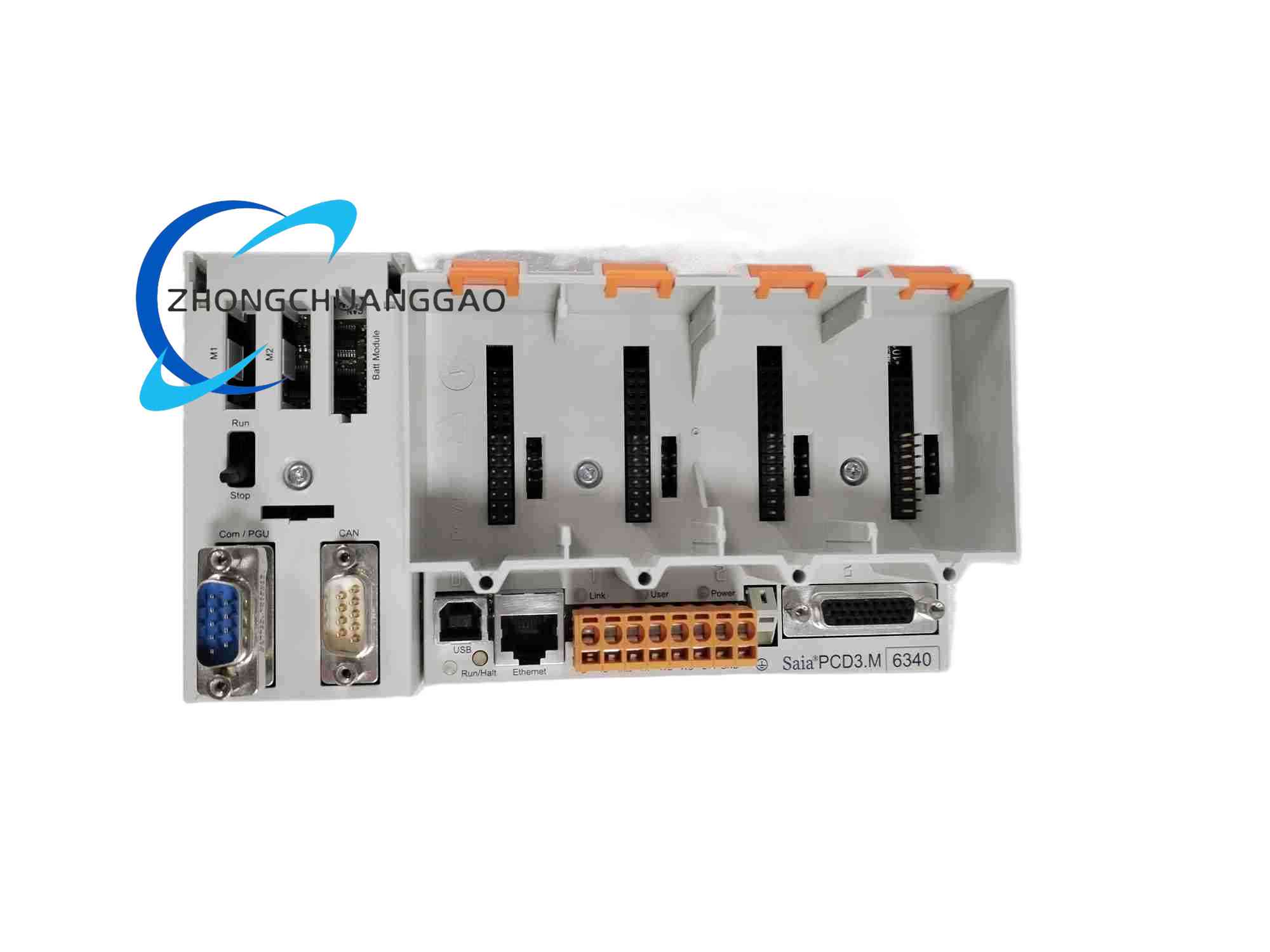
Description
Technical & Performance Parameters
- Total Universal Analog Input Channels: 8 multi-functional single-ended input channels
- Supported Multiple Input Signal Types: DC 0…10V, DC 0…2.5V voltage signals; DC 0…20mA, DC 4…20mA current loop signals; PT1000, NI1000 platinum thermal resistance temperature sensor signals
- A/D Conversion Resolution: 12-bit, full scale digital count range 0~4095
- Input Filter Time Constant: Two adjustable fixed modes, 7.8ms and 24.2ms selectable via internal jumper configuration
- Input Circuit Overvoltage Protection Threshold for Voltage Channels: Permanent ±40V DC withstand capability
- Input Circuit Overcurrent Protection Threshold for Current Channels: Permanent ±35mA DC withstand capability
- Full Scale Measurement Accuracy at 25°C Ambient Temperature: ±0.15% for voltage and current signal channels; ±0.2% for thermal resistance temperature measurement channels
- Repeatability Under Stable Laboratory Test Conditions: ±0.05% for all signal channel types
- Total Temperature Drift Error within 0°C~+55°C Continuous Operating Temperature Range: ±0.25% full scale range
- Single Channel Complete A/D Conversion Sampling Cycle: ≤2.4ms
- Galvanic Isolation Specification: 500V AC 1-minute withstand isolation between all field input signal circuits and the PCD3 internal expansion bus; no electrical isolation between adjacent 8 input channels
- Module Operating Power Supply: DC24V wide voltage input, allowable voltage fluctuation range DC19.2V ~ DC30V, total module power consumption less than 70mA under full 8-channel load operation
- Built-in EMC Protection Grade: Meet IEC 61000-6-2 industrial electromagnetic interference immunity standard
- Standard Equipped Accessories: Type A standard pluggable spring terminal connector block pre-installed on module terminal area
Function Features
- Multi-signal type software and jumper dual configurable channel function; each of the 8 input channels can be independently set to voltage input, current input or thermal resistance temperature measurement mode without hardware replacement, adapting to mixed multi-type sensor signal collection requirements on the same production site
- Dual-mode analog low-pass filter circuit with adjustable time constant; users switch between fast response 7.8ms filter mode and strong noise suppression 24.2ms filter mode via internal PCB jumpers according to field electromagnetic interference intensity and signal response speed demand
- Independent open-circuit and short-circuit fault detection logic for all current loop and thermal resistance channels; the module instantly generates dedicated fault flag signals and transmits alarm data to the PCD3 main CPU once sensor wiring breaks, thermal resistance wire open or current loop short-circuit faults occur
- On-board independent dedicated microcontroller chip undertakes all signal conditioning, filtering, temperature linearization calculation and engineering unit conversion tasks, completely separating heavy arithmetic computing tasks from the main PLC CPU to reduce system overall scan cycle delay
- Built-in dedicated thermal resistance linearization algorithm library for PT1000 and NI1000 temperature sensors; automatically correct non-linear temperature-resistance characteristic curves of thermal resistance components to output accurate linear temperature measurement values without manual curve compensation parameter configuration
- Front panel independent dedicated LED status indicator lamp for each of the 8 analog input channels; three distinct light states to display normal signal measurement, signal over-range threshold exceeding and channel wiring fault alarm conditions
- Support real-time bidirectional data interaction with the PCD3 system bus; the module automatically uploads all 8-channel instantaneous measurement values, channel working mode configuration data and all detected channel fault status data to the main CPU controller at fixed sampling cycles, and receives channel parameter reconfiguration commands issued by the CPU through the bus for online mode switching without powering off the module
Material Composition
- Outer Module Housing Shell: High impact resistance UL94-V0 flame retardant black ABS plastic material with surface anti-static and anti-corrosion coating treatment
- Main Control Printed Circuit Board: Double-layer high-density FR4 high temperature resistant fiberglass PCB board, gold plating treatment on all rear expansion bus gold finger contact pins to ensure long-term plugging anti-oxidation and stable low-resistance electrical connection
- Multi-Functional Spring Terminal Assembly: Pluggable multi-row spring cage quick wiring terminal blocks, conductive internal terminals made of nickel-plated high purity copper alloy material, insulating outer shell made of high temperature resistant PA66 flame retardant plastic
- Galvanic Isolation Components: High-speed linear optocoupler chips for electrical isolation between field multi-type signal circuits and internal digital bus circuits
- Precision Signal Conditioning Components: Low temperature drift metal film precision sampling resistors, high stability ceramic fixed filter capacitors and dedicated constant current drive chips for thermal resistance sensor measurement circuits
- Passive Heat Dissipation Components: Thin copper foil heat conduction patches attached to optocoupler chips and constant current drive chips for natural passive heat dissipation under full load continuous operation
Structural Characteristics
- Installation Mounting Form: Standard 35mm EN60715 DIN top hat rail horizontal clamping installation; vertical upside-down installation and side vertical installation are strictly prohibited
- Overall Module External Dimensions: Width 56mm, Height 97mm, Depth 72mm
- Front Panel Layout: 8 independent LED indicator lamps arranged in one-to-one correspondence with each analog input channel, a transparent detachable plastic dust-proof protective cover fully covering all spring wiring terminals to prevent industrial dust accumulation and accidental metal wire short-circuit faults; dedicated printed marking area on front panel for recording channel signal type configuration parameters for on-site maintenance convenience
- Internal Circuit Zoning Layout: Front PCB area arranges all 8 multi-type analog input signal conditioning circuits; middle PCB area arranges optocoupler galvanic isolation circuits and on-board microcontroller core operation circuits; rear PCB area arranges PCD3 proprietary expansion bus interface drive circuits; internal nickel silver alloy electromagnetic shielding partition plates separate analog weak signal circuit zones and digital high-speed bus circuit zones to eliminate mutual electromagnetic crosstalk interference
- Terminal Partition Layout: All 8 multi-functional analog input signal terminals concentrated on upper terminal row area; DC24V module operating power supply input terminals and dedicated shielding protective grounding terminals arranged at the rightmost independent terminal position to realize complete physical separation between power supply circuits and weak analog measurement signal circuits
- Rear Bus Connection Structure: Rear side of the module is equipped with proprietary PCD3 expansion bus gold finger connector, directly horizontally inserted into the slot of PCD3 series aluminum alloy multi-slot backplane rack, lock the module side plastic locking buckle to complete stable mechanical fixing and high-speed bidirectional data communication connection with the PCD3 main CPU controller
Working Principle
- Multi-Type Field Signal Input & Conditioning Process
Field sensors transmit different types of analog signals to the 8 input terminals of the PCD3.W340 module. According to pre-configured channel working mode (voltage, current or thermal resistance), the internal circuit automatically switches corresponding signal conditioning sub-circuits:
- Voltage signal mode: Input voltage signals pass through precision voltage division resistor networks and RC low-pass filter circuits to convert high-range input voltage into low-amplitude stable voltage signals suitable for A/D conversion chip input
- Current signal mode: Input 4-20mA or 0-20mA current loop signals flow through built-in precision sampling resistors to convert current variation into proportional analog voltage signals, then enter RC filter circuits to eliminate high-frequency industrial electromagnetic noise
- Thermal resistance temperature measurement mode: Built-in constant current drive chip outputs fixed micro constant current to PT1000/NI1000 thermal resistance sensors; thermal resistance resistance value changes linearly with ambient temperature, the constant current converts resistance variation into proportional voltage signals, then enters dedicated thermal resistance linearization correction circuits to eliminate non-linear temperature-resistance characteristic errors
After completing signal conditioning and noise filtering processing, all types of converted analog voltage signals enter linear optocoupler galvanic isolation circuits to cut off electrical connection between on-site field equipment and the internal digital control bus of the PLC system, completely eliminating ground loop current induced measurement signal distortion and interference.
- A/D Conversion, Data Calculation & Bus Transmission Process
The isolated stable analog voltage signal is sent to the built-in 12-bit high precision multi-channel A/D conversion chip, converting continuous analog electrical signals into discrete digital count values corresponding to signal magnitude. The on-board independent microcontroller chip reads all 8-channel digital conversion data in sequence, executes pre-configured multi-order moving average digital filtering algorithm and engineering unit scaling conversion calculation; for thermal resistance channels, additional dedicated linearization correction arithmetic operations are executed to output accurate linear temperature measurement values. All fully processed physical measurement data, channel working mode configuration parameters and real-time channel fault flag data are stored into the module local high-speed buffer memory area. At fixed unified system sampling cycles, the buffer stored data is transmitted to the PCD3 main CPU controller through the rear proprietary expansion bus; the CPU stores all channel measurement data into dedicated analog input image memory area for user control program logic judgment, closed-loop PID regulation calculation and production equipment interlock safety control logic execution.
- Multi-Type Channel Fault Real-Time Diagnosis Mechanism
Independent dedicated impedance and voltage detection sub-circuits are configured for each of the 8 input channels, operating continuously in parallel with normal signal sampling processes without occupying A/D conversion or microcontroller operation resources:
- Current loop channels: Continuously monitor the total loop impedance of the 4-20mA/0-20mA current circuit; when sensor wiring breaks or loop open-circuit occurs, loop impedance exceeds preset threshold value, trigger open-circuit fault flag signal
- Thermal resistance measurement channels: Real-time monitor thermal resistance loop impedance and voltage drop; detect thermal resistance wire open-circuit and short-circuit faults separately and generate corresponding independent fault flag signals
- Voltage input channels: Real-time monitor input voltage amplitude; when input voltage exceeds the preset upper over-range threshold or drops below lower limit threshold, trigger signal over-range fault flag signal
Once any channel fault condition is detected, the module instantly stores fault location channel number and fault type classification data into local buffer memory, synchronously lights up the corresponding channel LED fault indicator lamp on the front panel. In the next unified bus data transmission cycle, all fault flag data is uploaded to the PCD3 main CPU controller for permanent fault alarm record storage, real-time upper computer monitoring system alarm push notification and linkage safety interlock control logic execution to protect field production equipment from abnormal signal induced misoperation damage.
Reviews
There are no reviews yet.