
Product Short Description
Product Brief Introduction
The PCD2.M110 belongs to SAIA PCD2 compact PLC series, an all-in-one integrated controller integrating CPU, digital I/O, analog signal interface and multi-channel serial communication. It is positioned for small-scale decentralized automation, balancing compact footprint and complete control logic operation capability, serving as an upgrade alternative to entry-level micro PLCs with stronger expansion and communication compatibility.
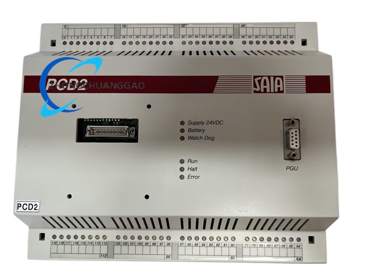
Description
Core Technical Specifications
- Processing Core & Memory
- Main Processor: 32-bit ARM Cortex-M4 industrial-grade microcontroller
- Program Flash Memory: 512 KB non-volatile flash storage
- Data RAM: 128 KB retentive working memory
- Retentive Variable Storage: Built-in lithium backup battery, retains variable data over 12 months without external power
- Integrated I/O Channel Configuration
- Digital Inputs: 14 channels, 24 VDC sinking/sourcing compatible, input single-channel max 10 mA
- Digital Outputs: 10 relay output channels (Form C mechanical relay), single-channel load capacity max 5 A resistive load
- Analog Inputs: 2 multi-functional analog input channels, support 0–10 V voltage / 4–20 mA current signals
- Communication Interfaces
- 1 x RS-485 terminal port, support Modbus RTU, S-Bus proprietary protocol
- 1 x USB Type-B programming port for PG5 engineering software program download
- 1 x D-Sub 9 pin serial auxiliary communication port (configurable RS232/RS485)
- Electrical Power Parameters
- Rated Supply Voltage: 24 V DC smoothed industrial power
- Operating Voltage Tolerance: 19.2 V DC ~ 30 V DC
- Max Power Consumption: 4.8 W
- Environmental & Mechanical Parameters
- Operating Ambient Temperature: -20 °C ~ +60 °C (natural convection mounting)
- Storage Temperature: -40 °C ~ +85 °C
- Relative Humidity: 5% ~ 95%, non-condensing
- Protection Class: IP20 (indoor cabinet installation only)
- Physical Dimensions (W × H × D): 110 mm × 90 mm × 60 mm
- Net Weight: 0.35 kg
- Certifications: CE, UL, CSA industrial safety certification
Function Features
- Complete IEC 61131-3 programming support, compatible with Ladder Diagram, Function Block Diagram, Structured Text, Sequential Function Chart programming languages via SAIA PG5 engineering software
- Multi-layer logic control capability, supports complex interlock, timing, counting, PID closed-loop analog regulation without external auxiliary modules
- Built-in multi-protocol communication stack, realizes data interconnection with HMI, frequency converters, sensors, upper monitoring SCADA systems
- Independent channel signal filtering circuit for analog inputs, automatically suppress industrial electromagnetic interference from power cables and motors
- Hardware fault self-diagnosis function, real-time detection of power undervoltage, relay output short circuit, communication bus disconnection, and output fault indicator light alarm
- Modular expandable architecture, supports stacking PCD3 series I/O expansion modules through S-Bus system bus to expand digital/analog I/O points
Working Principle
The PCD2.M110 operates under cyclic scan mode standard for PLC controllers. The 32-bit ARM core executes user-compiled logic programs in fixed scan cycles: first read all digital and analog input terminal signal states into internal input image register; second execute user control logic line by line, conduct mathematical operations, logic judgment, PID calculation based on input image data and internal retentive variables; third refresh all digital/analog output terminal states according to calculated output image register values. Independent communication coprocessor operates parallel to main logic scan, processing Modbus and S-Bus data exchange without occupying main CPU operation resources. All analog signals pass through isolated operational amplifier circuits before digital-to-analog conversion to eliminate ground loop interference between field sensors and controller mainboard.
Material Composition & Structural Characteristics
- Housing Material: High-strength flame-retardant ABS engineering plastic, UL94-V0 fire resistance grade, anti-static coating on internal housing wall to resist industrial static electricity
- Internal Circuit Board: Double-sided FR4 fiberglass PCB, full surface tin immersion treatment, industrial-grade surface mount components (SMD) for core control circuits
- Terminal Structure: Spring cage screw terminal blocks for I/O and power wiring, tool-free quick wire insertion design; D-Sub metal shielding shell for serial communication ports to block electromagnetic radiation interference
- Mounting Structure: Standard 35 mm DIN rail clamping buckle integrated at bottom housing, anti-drop locking structure to prevent sliding off rail under equipment vibration
- Heat Dissipation Structure: Vertical strip ventilation slits on top and bottom housing surfaces, natural air convection heat dissipation without built-in cooling fans (zero maintenance)
Installation Requirements
- Mounting Carrier: Must install on standard 35 mm DIN mounting rail inside closed industrial electrical cabinet
- Mounting Orientation: Vertical installation only, ventilation slits aligned vertically to guarantee convection air flow; horizontal or upside-down mounting is prohibited
- Cabinet Space Clearance: Maintain minimum 50 mm vertical empty space above and below the controller housing, minimum 20 mm horizontal gap between adjacent PLC modules to avoid heat accumulation
- Power Wiring Rules: Use twisted shielded cable for 24 V DC power supply, separate power wiring from high-current motor cable routing; install 3 A slow-blow fuse at front end of controller power circuit for short-circuit protection
- Grounding Standard: Connect controller functional ground terminal to cabinet protective earth busbar with 1.5 mm² cross-section copper wire, ground resistance ≤ 4 Ω
- Communication Cable Installation: RS-485 bus wiring must use 2-core twisted shielded cable, single bus length shall not exceed 1200 m, install 120 Ω terminal matching resistor at both physical ends of communication bus
Application Scenarios
- Building Automation: Small HVAC air-conditioning unit control, fresh air fan interlock, lighting group automatic control, water pump constant pressure regulation
- OEM Small Machinery: Packaging machine single-station logic control, conveyor belt speed interlock, small injection molding machine auxiliary axis control
- Environmental Monitoring: Sewage treatment small pool liquid level automatic control, waste gas exhaust fan linkage, temperature and humidity monitoring alarm
- Energy Monitoring: Small power distribution cabinet circuit breaker status collection, power meter Modbus data acquisition, peak valley load automatic switching control
Operation & Usage Precautions
- Do not install the controller in environments with corrosive gas, oil mist, conductive dust or direct water splash; IP20 protection cannot resist liquid intrusion
- Strictly prohibit connecting AC voltage to 24 V DC digital input terminals; overvoltage will permanently damage internal optocoupler isolation circuits
- Relay output channels cannot directly drive inductive loads (contactors, solenoid valves) without parallel freewheeling diode; inductive reverse voltage will ablate relay contact points rapidly
- When replacing backup lithium battery, complete power-off replacement within 30 seconds; long-time power loss will erase retentive variable data
- Avoid plugging/unplugging USB programming port and D-Sub serial communication port under live power state; hot plugging may damage internal communication transceiver chips
- Conduct regular quarterly maintenance: clean ventilation slits of accumulated dust with dry compressed air, check terminal screw tightness to prevent loose wiring contact resistance overheating
- Firmware upgrade must be executed via PG5 software with stable USB connection; power interruption during firmware flashing will cause controller mainboard program corruption and failure to boot
Reviews
There are no reviews yet.