
Product Short Description
Product Overview
This complete measuring system follows API 670 turbomachinery monitoring standard. PR6424 010-110 is standard-size eddy current probe with M10×1 mounting thread, paired with dedicated CON021 proximitor to convert clearance variation between probe tip and metal rotating shaft into linear DC voltage signal. It performs continuous online measurement of radial shaft vibration, axial thrust displacement, shaft eccentricity and differential expansion for heavy-duty rotating equipment.
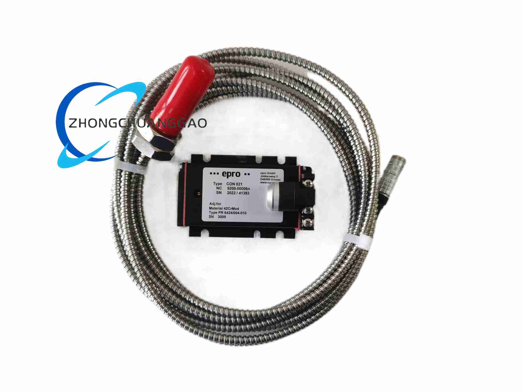
Description
Technical & Performance Specifications
- Probe Core Parameters
- Linear measuring range: ±2 mm (0~2mm full linear interval, suffix code 010 represents standard 2mm range)
- Probe total body length: 110mm (suffix code 110 stands for 110mm probe length)
- Probe head diameter: 10mm
- Standard integrated shielded coaxial cable length: 5m
- Matched system sensitivity: 8 V/mm
- Full system linearity error: ≤±1.5% full scale
- Frequency response bandwidth: DC ~ 10kHz
- Probe operating temperature: -40°C ~ +120°C
- Protection grade of probe body: IP65
- Standard measuring target: 42CrMo4 ferromagnetic alloy steel; minimum measured shaft diameter: 25mm
- CON021 Signal Conditioner Parameters
- Power supply input: 24VDC ±10% isolated power
- Standard output voltage: -4V ~ -20V DC; zero point output -12V
- Output load resistance requirement: ≥10kΩ
- Built-in self-diagnosis: automatic fault signal output for probe cable open circuit or short circuit
- Conditioner operating temperature: -20°C ~ +60°C
- Mounting form: standard 35mm DIN rail installation
- Protection grade: IP20
Material Composition & Structural Features
- PR6424 010-110 Probe
- Sensing coil: high-purity copper enameled wire winding, fully encapsulated with high-temperature two-component epoxy resin
- Probe housing: seamless 304 stainless steel tube, CNC precision machined external M10×1 mounting thread
- Connecting cable: double-layer shielded coaxial cable; inner insulation FEP fluoroplastic, outer braided copper shielding mesh, outer high-temperature resistant PVC sheath
- Cable connector: gold-plated self-locking LEMO aviation plug, anti-vibration locking structure
- CON021 Signal Conditioner
- Outer shell: flame-retardant PC plastic shell for DIN rail mounting
- Internal circuit substrate: FR4 glass fiber printed circuit board, integrated isolated power conversion, signal amplification and low-pass filter circuits
- Wiring terminals: spring-type copper alloy insulated terminals, compatible with wire cross-section 0.5~1.5mm²
Working Principle
CON021 generates stable high-frequency alternating electromagnetic field and transmits the signal to the coil inside PR6424 probe. When the probe tip approaches conductive metal rotating shaft surface, alternating eddy current will be induced on metal target surface. The magnetic field generated by eddy current counteracts the original magnetic field of probe coil, leading to regular impedance change of coil. The built-in demodulation circuit of CON021 detects impedance variation and converts it into linear analog DC voltage signal strictly proportional to clearance distance between probe tip and metal shaft. The output DC voltage signal contains static DC component reflecting average shaft position and dynamic AC component reflecting real-time shaft vibration. Meanwhile, the conditioner continuously monitors the conduction state of probe cable, and outputs fixed fault voltage signal once cable open circuit or short circuit occurs.
Core Functional Features
- Non-contact measuring mode, zero mechanical friction and wear between probe and rotating shaft, long service life
- Measuring signal will not be interfered by lubricating oil, water vapor, dust and impurity medium in bearing housing gap
- Wide temperature adaptability, stable measuring performance under high-temperature turbine and compressor bearing housing environment
- Complete matching measuring system with consistent factory calibration of probe and CON021 conditioner, guaranteeing overall linearity accuracy
- CON021 built-in cable fault self-diagnosis function, timely feed back probe circuit abnormal signal to upper monitoring system
- Standard linear voltage output signal, compatible with all industrial DCS, PLC, vibration protection monitoring equipment and data acquisition modules
- DIN rail centralized installation of CON021 conditioner, convenient for multi-channel vibration monitoring cabinet layout
- Standard 110mm length M10 thread probe, applicable to most medium and large turbomachinery bearing housing reserved mounting holes
Application Scenarios
- Steam turbine generator set radial shaft vibration and axial thrust displacement online monitoring
- Gas turbine rotor shaft eccentricity and dynamic vibration real-time measurement
- Large industrial centrifugal compressor, blower and fan shaft vibration protection monitoring
- Petrochemical plant high-speed process pump and screw compressor shaft displacement monitoring
- Hydraulic turbine generator unit rotating machinery fault early warning diagnosis system
- Marine heavy-duty diesel engine crankshaft axial thrust displacement monitoring
- Thermal power plant auxiliary rotating equipment vibration interlock protection system
Installation Requirements
- Probe Installation Rules
- Pass the probe through reserved threaded hole of equipment bearing housing, install two anti-loose lock nuts on probe external thread to prevent probe loosening caused by long-term equipment vibration
- Adjust initial clearance between probe sensing head and metal shaft target to midpoint of linear measuring range before tightening lock nuts
- Metal target surface area must reach at least three times of probe sensing head diameter to ensure stable eddy current signal excitation
- Keep installation position of probe at least 50mm away from strong electromagnetic interference sources including high-current power cables, AC contactors and driving motors
- Route probe shielded coaxial cable separately from power cables; fix cable with cable clamps to avoid repeated bending and tensile stress during equipment operation
- CON021 Conditioner Installation Rules
- Mount CON021 conditioner on standard 35mm DIN rail inside electrical control cabinet
- Maintain minimum 20mm vertical gap between adjacent CON021 conditioners to ensure natural heat dissipation
- Adopt independent isolated 24VDC power supply for vibration measuring signal conditioners; prohibit sharing power supply with high-power relay and contactor loads
- Use shielded twisted-pair cable for analog output signal wiring, single-point grounding of shielding layer at cabinet grounding copper bar
Operation & Maintenance Precautions
- Strictly prohibit scratching, collision and impact on probe sensing head surface; surface scratch damage will cause permanent measuring linearity deviation and invalidation of factory calibration
- Avoid excessive bending of probe integrated coaxial cable; minimum cable bending radius must not be less than eight times of cable outer diameter
- Perform full system measuring accuracy calibration every 12 months by using standard metal target displacement calibration fixture
- Regularly clean oil sludge, dust and carbon deposits accumulated on probe sensing head surface during long-term equipment operation; residual impurities will attenuate eddy current signal and reduce measuring stability
- When disassembling probe aviation plug, hold plug plastic shell for plugging operation, prohibit direct pulling of cable to prevent internal core wire breakage
- Do not install CON021 conditioner in cabinet area with poor ventilation and continuous high ambient temperature; install cabinet exhaust fan for forced cooling if long-term operating ambient temperature exceeds +55°C
- Once CON021 outputs fault alarm voltage signal, firstly check probe cable for breakage, short circuit and loose aviation plug connection before replacing any measuring components
-500x500.jpg)
Reviews
There are no reviews yet.