
Product Short Description
Product Overview
Description
Technical Performance Specifications
- Digital Input Channel Count: 16 independent fully isolated digital input channels, mutual channel isolation and field-bus side isolation
- Supported Input Signal Standard: 24VDC normally closed contact signal, recognition threshold: closed contact low level ≤5VDC, open contact high level ≥18VDC
- Channel Galvanic Isolation Voltage: 1500VDC isolation between each input channel and between field signal loop and FBM bus circuit
- Communication Interface: Dedicated Foxboro FBM field bus interface, with automatic hot-plug detection and 100ms communication heartbeat monitoring
- Power Supply Standard: Single-channel 24VDC industrial DC power input, built-in reverse polarity, overvoltage, undervoltage and surge multi-layer protection circuits
- Single Channel Protection Circuit: Independent TVS transient voltage suppression diode and current limiting resistor for each channel to resist industrial lightning surge and electromagnetic interference voltage impact
- Environmental Operating Parameters
- Operating Temperature Range: 0°C ~ +75°C
- Storage Temperature Range: -45°C ~ +90°C
- Vibration Resistance: Comply with IEC60068-2-6 industrial heavy vibration standard
- Humidity Resistance: 5%–95% non-condensing relative humidity
- Safety Certification Grade: Ex Zone2 explosion-proof certified, SIL1 functional safety integrity level compliant
- Physical Dimensions & Weight
- Dimensions: 165mm (H) × 85mm (W) × 105mm (D)
- Net Weight: 0.56kg
- Protection Rating: IP20, only applicable for installation inside sealed industrial control cabinets
Core Functional Features
- 16-Channel Normally Closed Contact Dedicated Acquisition Logic
All channels adopt built-in normally closed signal recognition algorithm, which prioritizes monitoring contact break state for safety interlock signals. Full electrical isolation design eliminates cross-channel signal interference and single-channel abnormal high voltage reverse damage to bus communication circuit.
- High Anti-Interference Industrial Signal Acquisition Performance
Each channel equipped with independent surge suppression and current limiting protection circuits, effectively absorbing instantaneous high surge voltage generated by field lightning, high-power motor start-stop and frequency converter switching, avoiding signal state misjudgment caused by strong electromagnetic noise.
- 5ms Fixed Cycle Real-Time Channel State Upload
The module samples the break/make state of 16 normally closed contact channels at a fixed 5ms sampling cycle, packs all channel status data into standard FBM bus data frames and transmits to RH100CP master controller in real time, realizing delay-free capture of instantaneous normally closed contact state changes of field safety interlock equipment.
- Independent Single-Channel Real-Time Fault Diagnosis & Precise Location
Continuous monitoring of loop voltage of each input channel during normal operation. When open circuit, short circuit or overvoltage fault occurs in a single channel, the module generates unique single-channel fault code, uploads to master controller via FBM bus, and lights the corresponding channel fault LED on front panel to guide maintenance personnel to quickly locate faulty signal wiring.
- Configurable Communication Loss Fail-Safe Diagnosis State
When FBM bus heartbeat signal loss exceeds 3 seconds, all 16 normally closed input channels are locked to pre-configured open-circuit high-level diagnosis state, continuous uploading of communication loss fault alarm information to RH100CP until bus communication heartbeat signal recovers.
- Full Power-On BIST Hardware Self-Test Function
After 24VDC power supply access, module automatically executes complete BIST self-test program, sequentially inspecting FBM bus drive circuit, all 16 normally closed input channel optocoupler acquisition circuits, multi-layer power supply protection circuits and channel fault diagnosis monitoring circuits. All detected hardware fault information is uploaded to RH100CP immediately, with module public fault alarm LED illuminated synchronously.
- Remote Online Firmware Upgrade Support
Supports remote online underlying firmware program update via FBM bus initiated by RH100CP master controller. Firmware upgrade process does not require module power-off or DIN rail disassembly, all field normally closed contact signal wiring can remain connected during upgrade. If firmware data packet transmission is abnormally interrupted, module automatically rolls back to original stable firmware version to avoid bus communication function failure.
- Channel Independent LED Status Indication Design
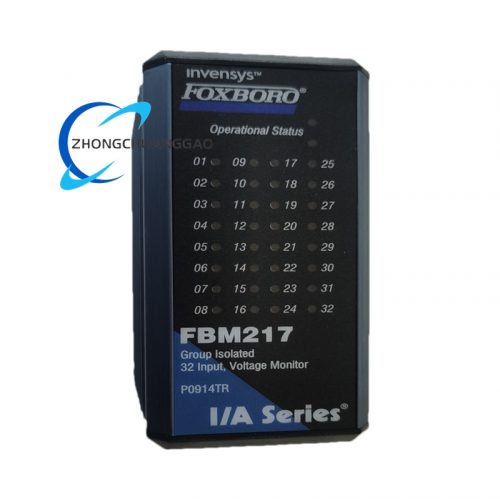
Front panel equipped with independent small LED indicator for each of 16 normally closed input channels: LED keeps steady on when field normally closed contact is disconnected (safety alarm state); LED keeps off when field contact remains closed (normal operation state). Maintenance personnel can quickly judge real-time state of field safety interlock contacts through front panel LED indicators without logging into central DCS operation monitoring station.
- Compact Low Power Cabinet Layout Design
Compact small-size structural design, occupying small DIN rail space inside control cabinet, supporting dense multi-module parallel installation layout. Ultra-low static operating power consumption avoids excessive heat accumulation when multiple RH916NC modules are installed in parallel inside sealed cabinet, eliminating hidden danger of module overheating and communication failure caused by heat accumulation.
- Built-In FBM Bus Hot-Plug Fault Tolerant Detection Circuit
Dedicated hot-plug detection circuit integrated inside module. When module is plugged into or pulled out of FBM bus wiring terminals under power-on state, hot-plug detection circuit immediately sends module access/disconnection event notification data packet to RH100CP master controller via FBM bus, master controller automatically marks module offline/online state synchronously on central DCS monitoring interface.
Application Scenarios
- Petrochemical Safety Interlock Signal Collection
Crude oil distillation unit emergency stop normally closed contacts, reactor overpressure safety valve normally closed feedback switches, fire control damper normally closed limit contacts, combustible gas detection interlock normally closed discrete signal acquisition.
- Thermal Power Plant Safety Protection System Monitoring
Boiler emergency trip normally closed auxiliary contacts, feed water pump fault normally closed alarm contacts, flue gas desulfurization safety baffle normally closed limit switches, circulating water pipeline leakage normally closed detection contact signal acquisition.
- Fine Pharmaceutical Production Safety Control
Reactor over-temperature safety interlock normally closed contacts, purification workshop fire alarm normally closed trigger contacts, raw material delivery pipeline emergency cut-off valve normally closed feedback signal acquisition.
- Metallurgical Smelting Equipment Safety Monitoring
Blast furnace cooling water pipeline over-temperature normally closed safety contacts, hot rolling mill equipment emergency stop normally closed auxiliary contacts, aluminum electrolysis pot overpressure safety interlock normally closed discrete signal acquisition.
- Municipal Sewage & Tap Water Safety Automation
Aeration tank stirrer fault normally closed alarm contacts, filter pool overpressure safety valve normally closed feedback switches, pipeline emergency cut-off valve normally closed limit contact signal acquisition.
Material Composition & Structural Characteristics
- Outer Shell Material
UL94-V0 flame retardant reinforced ABS plastic shell, built-in thin copper electromagnetic shielding layer to isolate mutual interference between signal channels. Surface coated with anti-static coating to prevent static charge accumulation in dry closed cabinet environments. Horizontal heat dissipation slots reserved on upper and lower shell surfaces for passive heat dissipation of internal optocoupler circuits.
- Internal Circuit Board
Double-sided high-temperature resistant FR4 printed circuit board. Each normally closed input channel is equipped with independent isolated optocoupler circuits separated by physical insulating partitions. All signal pin terminals adopt thick gold plating process to resist industrial dust, moisture and weak corrosive gas erosion, ensuring long-term stable contact performance.
- Terminal Partition Layout Design
Terminal base completely separates single-channel 24VDC power supply terminals and 16 normally closed digital input signal terminals with color-coded partition marks. Clear printed channel number identification labels eliminate field wiring misconnection risks.
- DIN Rail Mounting Structure
Standard 35mm top-hat DIN rail clip-on fixed structure with dual-side integrated locking buckles, preventing module sliding and falling off DIN rail under long-term continuous industrial equipment vibration.
- Front Panel Multi-Group LED Indicator Layout
16 independent normally closed channel status LED indicators, public power running LED, general hardware fault alarm LED and FBM field bus communication running LED. Ultra-high brightness long-life lamp beads adopted, LED status can be clearly identified under low-light closed control cabinet environments.
Working Principle
- Dual-Stage Isolated Power Conversion Stage
Single 24VDC industrial DC power input passes through multi-layer overvoltage, reverse polarity and surge protection circuits, then divided into two groups of isolated low-voltage power: 5V isolated power supply for 16-channel optocoupler signal acquisition circuits, 3.3V isolated power supply for FBM field bus communication chip. Independent isolated power loops completely eliminate power supply noise interference to weak field normally closed contact signal acquisition circuits.
- Normally Closed Contact Signal Sampling & Optocoupler Isolation Stage
Each normally closed 24VDC contact signal from field safety interlock equipment flows through channel independent TVS surge suppression diode and current limiting resistance circuit, then drives isolated optocoupler component to convert analog voltage contact signal into isolated digital logic signal. The module sequentially samples logic status of all 16 normally closed input channels at fixed 5ms sampling cycle, temporarily storing sampled channel status data into local buffer memory chip.
- FBM Field Bus Real-Time Data Transmission Stage
Packaged real-time normally closed contact break/make status data is transmitted to RH100CP core control processor through dedicated FBM field bus communication channel. Module sends fixed 100ms cycle communication heartbeat data packets to maintain stable bus connection with master control processor.
- Single-Channel Loop Fault Continuous Diagnosis Stage
Dedicated hardware monitoring circuit continuously detects real-time loop voltage value of each of 16 normally closed input channels during normal module operation. When single channel open-circuit disconnection fault, short-circuit grounding fault or abnormal overvoltage fault is detected, fault diagnosis circuit generates unique single-channel fault identification code, packs fault code into FBM bus data frame and uploads to RH100CP master controller, simultaneously illuminating corresponding channel fault LED indicator on module front panel to remind on-site maintenance personnel of specific faulty signal wiring channel.
- FBM Bus Communication Loss Fail-Safe Protection Stage
When communication heartbeat data packet exchange between RH916NC module and RH100CP master controller via FBM field bus is interrupted for more than 3 consecutive seconds, module internal fail-safe logic circuit locks all 16 normally closed digital input channels to pre-configured open-circuit high-level safety diagnosis state, continuously uploading bus communication loss fault alarm data packets to RH100CP master controller through FBM bus until bus communication heartbeat signal exchange recovers to normal state.
- Power-On Full BIST Hardware Self-Test Execution Stage
After single-channel 24VDC industrial DC power supply is connected to module power terminals, module automatically executes complete full-range BIST hardware self-test program, sequentially verifying FBM field bus communication drive circuit, all 16 normally closed input channel optocoupler signal acquisition circuits, multi-layer power supply overvoltage/reverse polarity/surge protection circuits and single-channel loop fault diagnosis monitoring circuits. All hardware fault information detected during self-test execution is immediately uploaded to RH100CP core control processor via FBM field bus, with module public general hardware fault alarm LED indicator on front panel illuminated synchronously.
Installation Requirements
- Installation Environment Restrictions
Must be installed inside fully sealed industrial electrical control cabinet with IP54 or higher protection grade. Open workshop open-air installation, direct exposure to industrial corrosive gas, oil mist, high-temperature hot air, water vapor and heavy dust environments is strictly prohibited.
- DIN Rail Horizontal Mounting Standard
Horizontal installation on standard 35mm top-hat DIN rail inside control cabinet. Maintain minimum 15mm horizontal heat dissipation gap between RH916NC module and adjacent modules on left and right sides to ensure sufficient passive heat dissipation space for internal optocoupler signal acquisition circuits. Vertical installation gap above and below module on DIN rail shall not be less than 40mm to avoid heat accumulation between upper and lower stacked modules.
- Standard Wiring Specification Rules
- Power Supply Cable Wiring: 0.75–1.5mm² shielded industrial control cable for single-channel 24VDC power supply terminals. Cable shielding layer single-point grounded on cabinet main protective grounding busbar to eliminate power supply cable electromagnetic interference noise.
- Normally Closed Digital Input Signal Cable Wiring: 0.5–1.0mm² shielded twisted pair control cable for all field normally closed contact signal wiring. High-current power cables and weak field signal cables shall be laid in independent separated wire ducts inside control cabinet, minimum separation distance between two types of wire ducts shall not be less than 10cm to avoid strong electromagnetic interference generated by high-current power cables affecting stable signal sampling accuracy of normally closed contact channels.
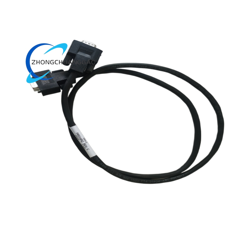
- FBM Field Bus Communication Cable Wiring: Special Foxboro dedicated shielded field bus twisted pair cable for FBM bus wiring between RH916NC module and RH100CP control processor. Cable shielding layer single-point grounded on cabinet main grounding busbar to suppress external industrial frequency conversion equipment and high-power motor electromagnetic interference noise.
- Module Shell Grounding Specification Standard
Module shell dedicated grounding terminal connected to industrial control cabinet main protective grounding busbar with short copper wire of length less than 25cm. Cabinet grounding circuit overall grounding resistance value shall be strictly controlled below 3Ω to ensure effective release of static charge accumulated on module shell and eliminate external electromagnetic interference noise coupling to internal signal acquisition circuits.
- FBM Bus Node Address Pre-Configuration Before Power-On
3-bit rotary digital address switch reserved on module side housing to set unique independent node identification address of RH916NC module on FBM field bus network. Module only reads address value set by rotary switch during initial power-on startup process. Any modification to rotary address switch position requires full module power cycle restart operation to make new node address configuration take effect on FBM bus network.

Reviews
There are no reviews yet.