
Product Short Description
Product Introduction
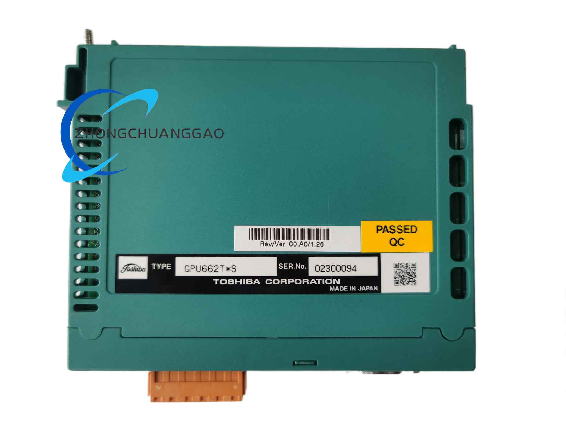
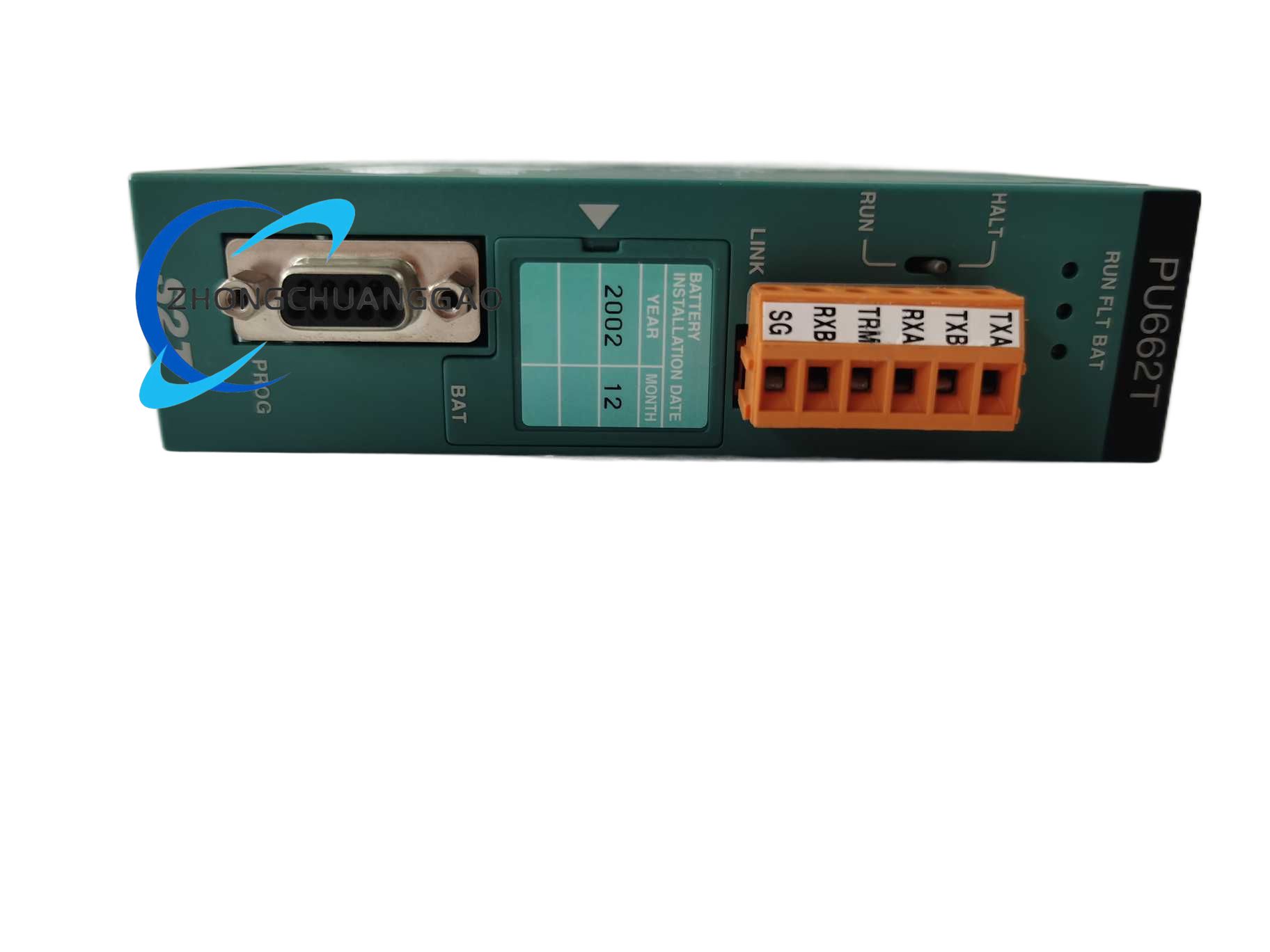
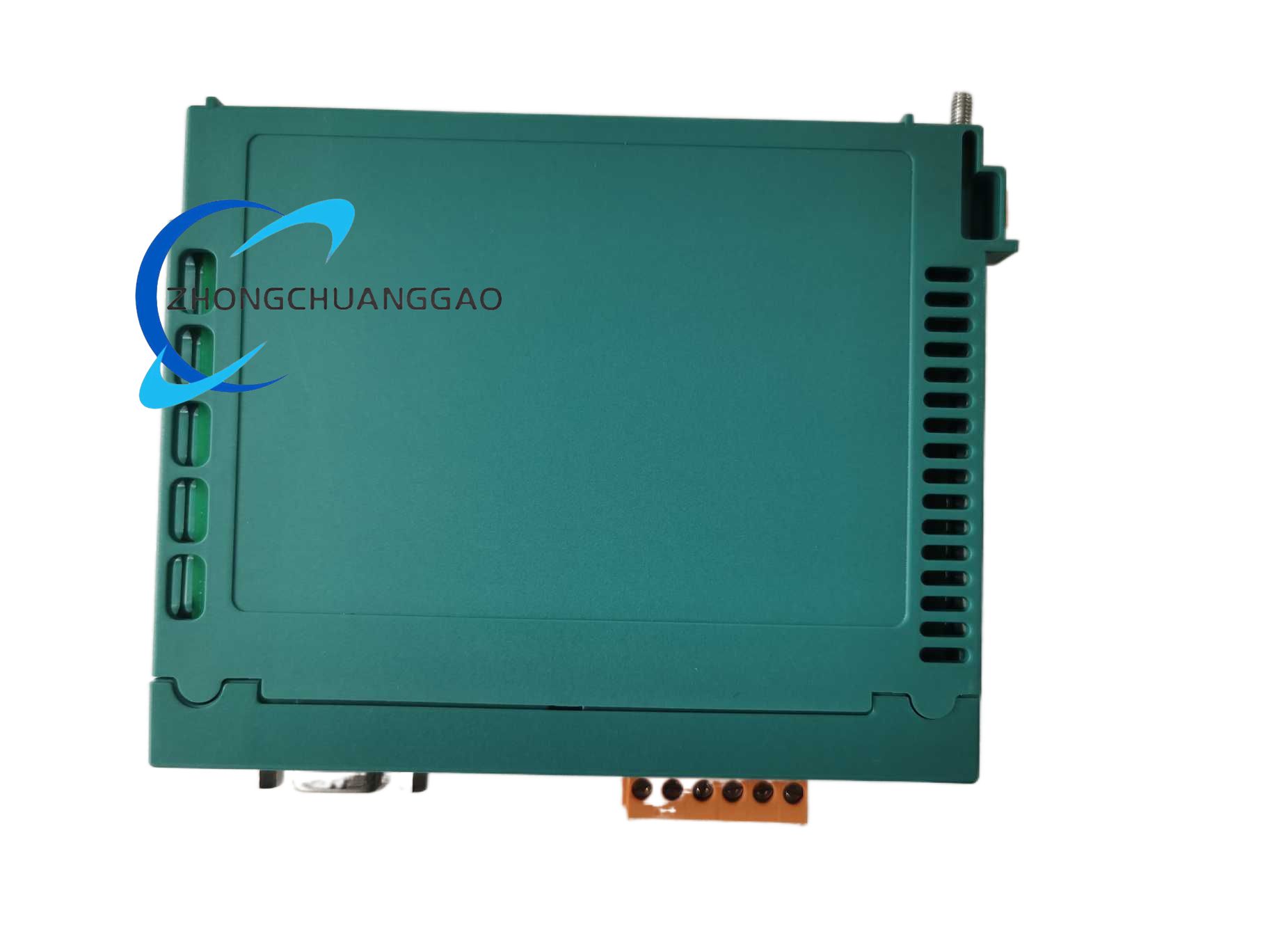
Description
Core Technical Specifications
Electrical Input Parameters
Input no-load power consumption: Max 8 VA
Full load power conversion efficiency: 87% minimum
Input surge withstand capability: 2kV AC transient grid surge
Multi-Channel Stabilized DC Output Parameters
Channel 2: +15 VDC, maximum output current 0.8 A, for analog signal operational amplifiers
Channel 3: -15 VDC, maximum output current 0.8 A, for differential current sampling circuits
Channel 4: +5 VDC, maximum output current 2.5 A, for main control CPU, logic chips and communication circuits
All output channels achieve galvanic isolation between primary AC input side and secondary DC output side, isolation withstand voltage 2500 VAC for 1 minute.
Physical & Mechanical Parameters
Net weight: 240 g
Mounting mode: Fixed installation inside Toshiba inverter chassis via M3 metal self-tapping screws
Terminal connection: Plastic integrated pin header socket, direct plug-in docking with inverter main control board wiring harness
Environmental Operating Parameters
Storage temperature range: -35 ℃ to +75 ℃
Relative humidity: 5% to 90% non-condensing
Protection grade: IP20 for internal installation inside sealed inverter cabinet
Vibration resistance: Compliant with IEC 60068-2-6, 10–120 Hz continuous vibration without loose solder joints
Certification Standards
EMC certification: CE Class B internal component electromagnetic compatibility standard
RoHS industrial electronic hazardous substance restriction compliance
Function & Feature Highlights
- Multi-channel independent stabilized DC output design, each output channel equipped with independent secondary side overcurrent and short-circuit protection circuit. When a single output channel suffers short-circuit fault, only the faulty channel stops output, other voltage channels maintain normal power supply to avoid full inverter shutdown caused by single circuit fault.
- Wide grid voltage adaptation capability, stable DC voltage output can be maintained under 180–264 VAC grid fluctuation, fully adapting to factory power grid with large voltage drop during peak production periods.
- Built-in primary side input undervoltage detection circuit. When grid input voltage drops below 170 VAC continuously for more than 500ms, the module automatically sends undervoltage fault signal to inverter main CPU, triggering inverter soft shutdown protection to prevent damage to control chip caused by unstable low voltage power supply.
- High-temperature automatic power derating logic. When the internal temperature of the power module rises above 55 ℃, the module automatically reduces maximum output current by 20% to lower internal power loss and heat generation, avoiding thermal breakdown of switching power tubes.
- Integrated EMI suppression filter circuit at AC input terminal, effectively attenuating high-frequency electromagnetic noise generated by inverter main power rectifier and IGBT power tubes, eliminating control signal distortion and communication failure caused by power supply electromagnetic interference.
- Compact integrated PCB layout, all power circuit components are arranged with standardized heat dissipation intervals, no auxiliary cooling fan required, relying on natural convection heat dissipation inside the inverter chassis, zero mechanical wearing parts to extend service life.
Material & Structural Composition
- Main Circuit Substrate: Double-sided high Tg FR4 flame-retardant copper-clad circuit board, thickened copper foil layer for high-current power loop circuits to reduce conduction heat generation.
- Power Semiconductor Core Components: High-frequency MOSFET switching power tubes, fast recovery rectifier diodes and low ripple output electrolytic capacitors imported from Japanese electronic component manufacturers.
- Isolation Components: High insulation withstand voltage high-frequency pulse transformer with multi-layer mica isolation paper wound between primary and secondary winding coils, realizing complete electrical isolation between input and output circuits.
- External Structural Auxiliary Materials: Black flame-retardant ABS plastic pin header terminal base, UL94 V-0 fire resistance rating; all fixing hardware adopts zinc-plated carbon steel screws with anti-rust surface treatment.
- Heat Dissipation Auxiliary Materials: Aluminum alloy heat sink attached to high-power switching power tubes, thermally conductive silicone pad between heat sink and power tube to reduce thermal contact resistance and accelerate heat conduction dissipation.
Working Principle
- AC Input Rectification Stage: The alternating current voltage extracted from the inverter main circuit enters the PU662T module’s EMI filter circuit first to filter grid high-frequency interference noise. The filtered AC voltage is converted into high-voltage direct current through full-bridge rectifier and primary side filter electrolytic capacitor.
- High-Frequency Switching Conversion Stage: The high-voltage DC power supply drives the high-frequency MOSFET switching tube to perform high-frequency on-off switching action controlled by PWM pulse width modulation chip. The pulse voltage generated by switching action is transmitted to each secondary winding coil of the isolation pulse transformer through electromagnetic induction energy transfer.
- Multi-Channel DC Voltage Stabilization Stage: The alternating pulse voltage induced by each secondary winding coil passes through independent fast recovery rectifier diode and low ESR filter capacitor group to complete rectification and filtering, generating four groups of different specification rough DC voltages. Each channel is equipped with linear voltage stabilization and feedback sampling circuit, which collects real-time output voltage value and feeds it back to the primary side PWM control chip to adjust switching pulse duty cycle, realizing constant stabilized DC voltage output under load fluctuation.
- Multi-Layer Hardware Protection Execution Stage: Dedicated sampling circuits monitor primary input voltage, secondary output current and internal module temperature in real time. When undervoltage, overcurrent, short-circuit or overtemperature abnormal threshold is triggered, the protection circuit instantly locks the PWM driving signal of the switching power tube, cuts off energy transmission of the pulse transformer, and sends digital fault signal to the inverter main control board to record fault codes and trigger equipment protection interlock.
Application Scenarios
- Toshiba VF-AS1 heavy-duty industrial frequency converter for metal rolling mill, mine hoist and water pump fan drive equipment
- Toshiba VF-PS1 general-purpose inverter for automated production line conveyor belts, packaging machinery and small hydraulic equipment
- Central air-conditioning refrigeration unit circulating water pump inverter internal control power supply
- Chemical plant corrosion-resistant centrifugal fan variable frequency drive control system internal power supply component
Installation Requirements
- Inverter Internal Fixed Mounting: Place the PU662T power module into the reserved installation slot inside the Toshiba inverter chassis, align the four screw fixing holes of the module with the chassis metal fixing support, tighten four M3 self-tapping screws with torque controlled at 0.6 N·m to prevent loose screws caused by equipment operation vibration.
- Wiring Harness Plug Connection Standard: Align the plastic pin header socket of the module with the matching wiring harness plug of the inverter main control board, push the plug straight into the socket until the plastic buckle clicks to lock the plug, avoid inclined plug-in operation which may bend internal metal pins and cause open circuit contact failure.
- Chassis Environmental Installation Conditions: Ensure the inverter chassis is equipped with unobstructed top and bottom air convection ventilation channels, do not block the module aluminum heat sink with internal wiring harnesses or cable ties, maintain at least 15 mm vertical ventilation gap above and below the power module.
- Grid Input Wiring Specification: The AC input wire connected to the module must use copper wire with cross-section not less than 0.75 mm², wire stripping length controlled at 6 mm, ensure metal wire core fully inserted into the terminal crimping groove of the wiring harness plug without exposed copper strands causing short circuit risk.
Usage & Maintenance Precautions
- Static Discharge Protection Operation Standard: Wear anti-static wristband reliably connected to inverter chassis protective earth bar before disassembling, plugging or inspecting the PU662T module; static electricity from human body will permanently damage the sensitive PWM control chip on the module circuit board.
- Pre-Power-On Inspection Requirement: After completing module installation and wiring harness plug connection, visually inspect all pin header metal pins for bending deformation, foreign metal debris bridging adjacent pins; manually shake the wiring harness plug slightly to confirm no loose plug phenomenon before switching on inverter main power supply.
- Regular Preventive Maintenance Cycle: Every 12 months for continuous 24-hour operation equipment, every 24 months for intermittent operation equipment; cut off all inverter main power supply and wait for 30 minutes to release residual charge of internal high-voltage capacitors before disassembly inspection; use dry anti-static soft brush to clean dust accumulated on circuit board, heat sink and pin header terminals, strictly prohibit compressed air high-pressure blowing which will push conductive dust into chip pin gaps and cause short-circuit failure.
- Strict Load Matching Restriction: Do not modify the inverter internal circuit to add extra external electrical loads on any DC output channel of the PU662T module; exceeding the rated maximum output current of the channel will continuously trigger overcurrent protection, long-term overload operation will burn internal rectifier diodes and switching power tubes permanently.
- Prohibited Operating Conditions & Operations: Do not install the inverter equipped with PU662T module in environments with continuous oil mist, conductive metal dust, corrosive acid and alkali gas or high humidity condensation; do not input AC voltage exceeding 264 VAC to the module input terminal, overvoltage will break down primary side filter capacitors and isolation transformer winding insulation layers; disassembly of the module circuit board without professional Toshiba maintenance authorization is forbidden, disassembly will destroy internal voltage feedback and protection circuit layout, and the module will lose original protection performance.
- Spare Module Storage Requirements: Store unused spare PU662T modules in sealed anti-static packaging bags, placed in constant temperature 15–25 ℃ dry storage cabinet; avoid long-term storage in high temperature, high humidity or chemical corrosion environment to prevent circuit board copper foil oxidation and electrolytic capacitor capacity attenuation.
Reviews
There are no reviews yet.