
Product Short Description
Product Introduction
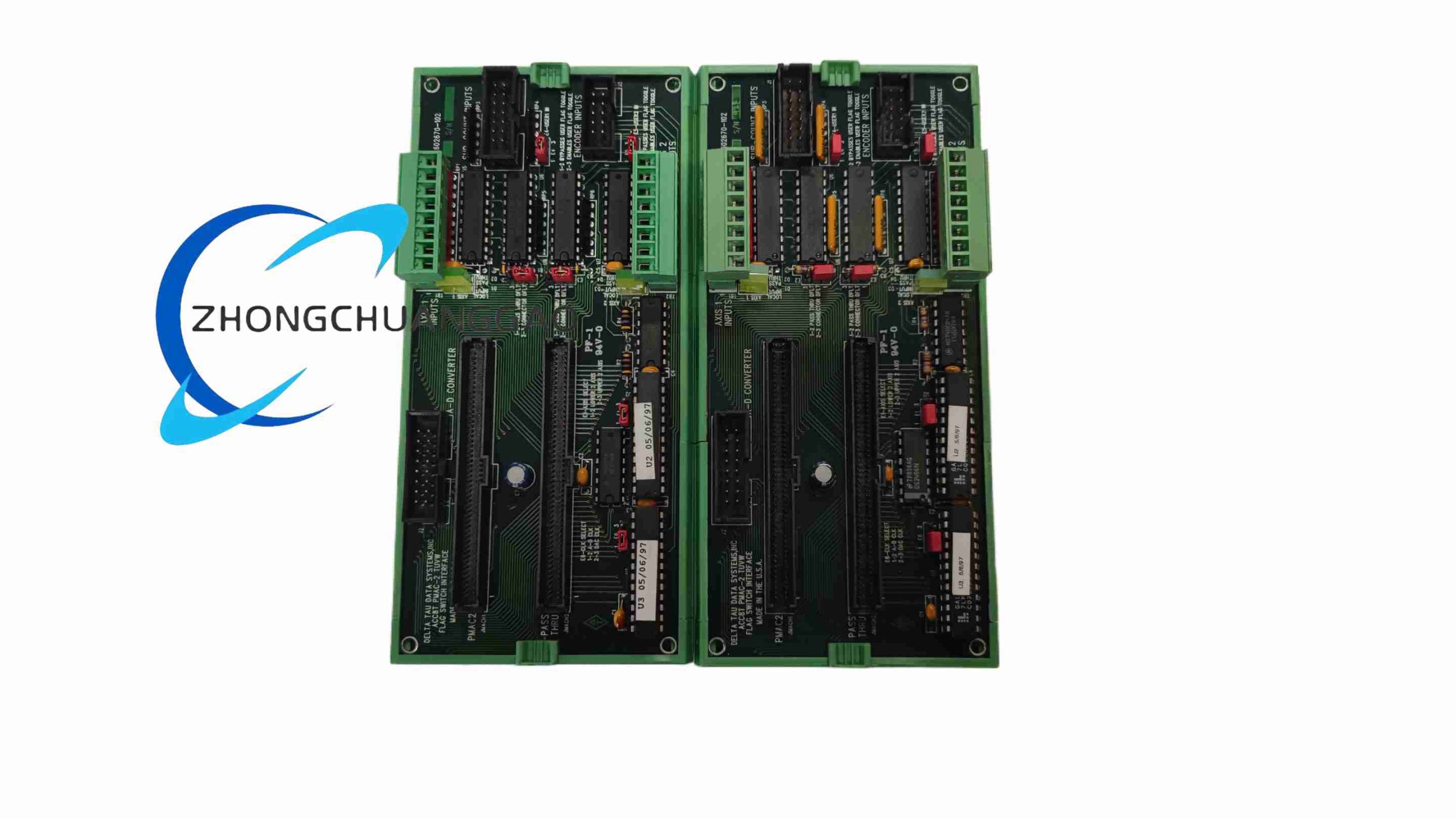
ACC-8T is an auxiliary signal multiplexer daughterboard developed for PMAC2 series motion control systems. It is installed as a pass-through intermediate board between PMAC2 main CPU and ACC-8S / ACC-8A axis interface boards. Its core function is to multiplex multiple groups of auxiliary digital flag signals (T, U, V, W, USER flags) for each motion axis, allowing single axis channels to switch between multiple sensor signal groups dynamically during machine operation. It is a mandatory matching board for systems requiring hall-effect motor commutation signals and analog encoder sub-count interpolation feedback simultaneously on the same axis channel.
Description
Core Function Features
- Pass-through signal architecture: All primary axis pulse, encoder, limit/home signals fully pass through without signal attenuation
- Per-axis multi-channel digital flag multiplexing circuit supporting T/U/V/W/USER five groups of auxiliary input signals
- Dedicated header interface for connection with ACC-28B multi-channel analog-to-digital converter boards
- Onboard terminal block headers for direct wiring of hall-effect commutation sensors and analog encoder interpolator sub-count signal outputs
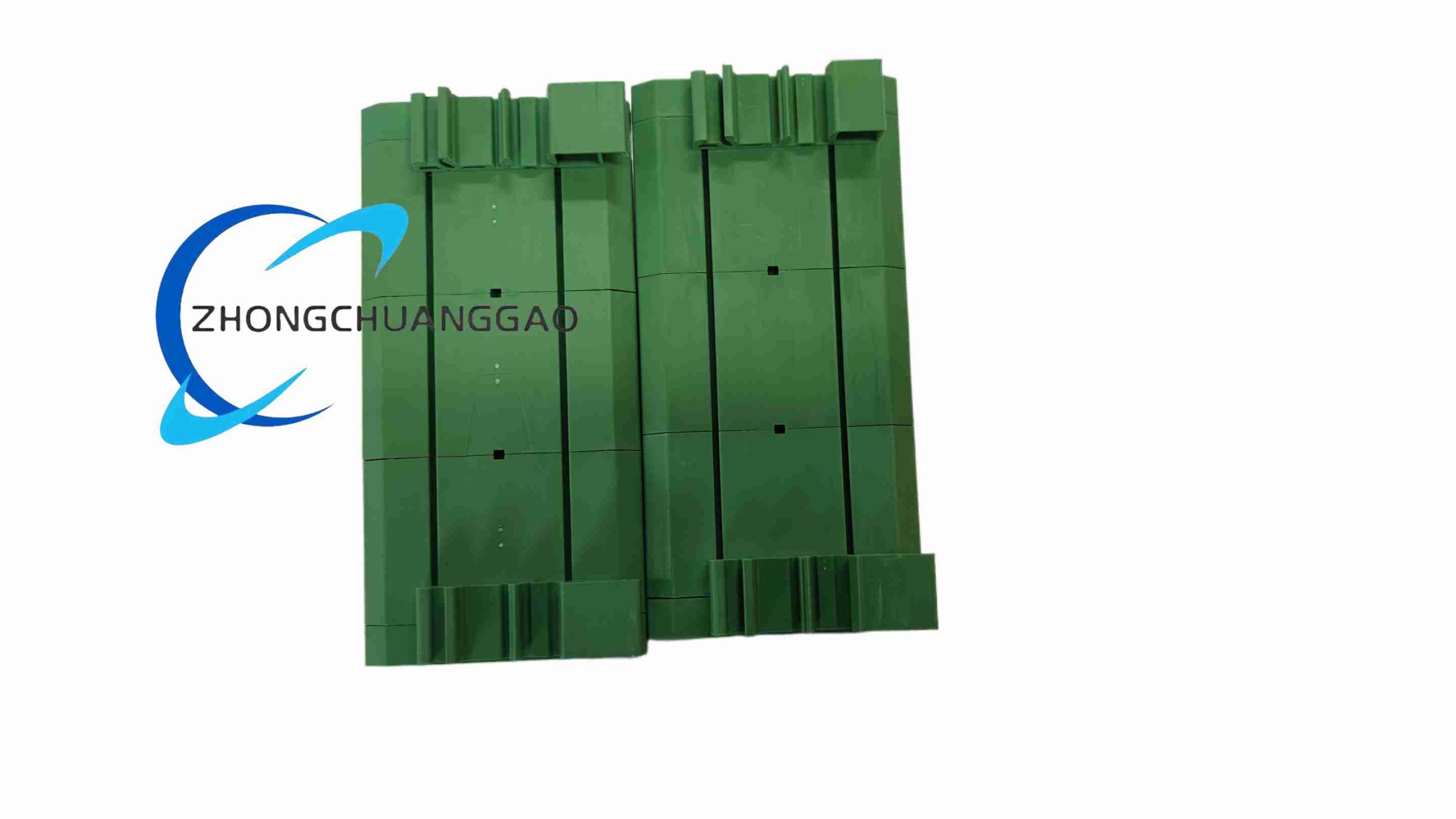
- DIN rail mounting option (Option-1 factory configuration) for standalone cabinet installation without stackable connection
- Hardware signal switching logic controlled by PMAC2 motion program variables, no manual DIP switch adjustment required during operation
- Low signal delay multiplexing circuit with maximum 400 ns signal switching latency, no impact on high-speed closed-loop servo performance
Technical & Performance Specifications
表格
| Parameter | Standard Value |
|---|---|
| Supported Axis Multiplex Channels | 8 axis multiplexing groups, matching ACC-8 series 8-axis layout |
| Auxiliary Flag Input Channels Per Axis | 5 groups (T, U, V, W, USER) |
| Signal Switching Latency | Max 400 ns |
| Digital Input Logic Voltage Range | 5 VDC / 24 VDC dual-mode compatible |
| Analog Expansion Interface | Dedicated header for ACC-28B 16-bit ADC boards |
| Operating Power Consumption | 650 mA @ +5V DC, 40 mA @ ±12V DC |
| Operating Temperature Range | 0°C ~ +60°C |
| Storage Temperature Range | -20°C ~ +70°C |
| Relative Humidity | 10% ~ 95% non-condensing |
Material Composition & Structural Characteristics
- PCB Substrate: FR4 industrial high-temperature resistant printed circuit board, gold-plated signal contact pins for long-term stable signal transmission
- Multiplexing Core Components: High-speed CMOS analog multiplexer ICs with low on-resistance signal channels
- Connector Parts: Flat cable stack header for PMAC2/ACC-8 series pass-through connection, screw terminal blocks for field sensor wiring
- Mechanical Structure: Standard Eurocard stackable form factor; Option-1 version equipped with DIN rail plastic buckle clip for independent cabinet rail mounting
- Physical Dimensions: 162 mm (L) × 118 mm (W) × 25 mm (T); Net weight: 380 g
Working Principle
ACC-8T adopts a serial pass-through hardware layout. Primary motion control signals (pulse/direction, encoder feedback, limit/home switches) flow directly through the board’s internal copper traces without signal processing or delay. Auxiliary sensor signals (hall-effect motor commutation, analog encoder interpolation sub-count signals) are wired to ACC-8T’s per-axis multiplex input terminals. PMAC2 motion programs send digital logic control signals to ACC-8T’s onboard multiplexer ICs to dynamically switch which group of auxiliary flag signals is transmitted to the ACC-8 series axis board at any given time. During machine power-up initialization, the multiplexer switches to hall-effect sensor input for motor phase commutation calibration; during normal high-speed operation, the multiplexer switches to analog encoder interpolator sub-count signals to achieve ultra-fine position subdivision resolution. All multiplexed auxiliary signals are optically isolated before transmission to eliminate external sensor electrical noise interference.
Installation Requirements
- Stacked Installation (Standard Configuration): Install ACC-8T as an intermediate pass-through board between PMAC2 main controller and ACC-8S/ACC-8A axis board; connect three boards sequentially with factory-supplied flat ribbon cables before rack installation
- DIN Rail Installation (Option-1 Version): Mount directly on standard 35 mm DIN rail inside IP54 minimum protection electrical cabinet; install adjacent to ACC-28B analog ADC boards for short analog signal wiring length
- Wiring Separation Rules: Separate low-voltage auxiliary sensor signal wiring from high-power servo drive power cables with minimum 15 cm clearance; all analog encoder interpolation signal wiring must use shielded twisted-pair cable with single-end shielding grounding
- Grounding Specifications: Connect board metal shielding frame to cabinet PE protective earth ground with 2.5 mm² copper wire; implement single-point grounding for all PMAC2 series expansion boards in the control rack
- Power Supply Matching: Use regulated low-ripple ±12V DC and +5V DC power supply for board operation, maximum allowable ripple voltage 50 mV
Application Scenarios
- High-precision optical inspection equipment: Laser interferometer positioning stages, CCD camera scanning motion axes requiring dual hall-effect and analog encoder feedback
- High-speed CNC machine tools: High-precision spindle positioning axes with sinusoidal AC servo motor hall commutation and sub-micron encoder subdivision
- Semiconductor lithography equipment: Reticle transport multi-axis stages requiring dynamic switching between initialization commutation signals and runtime high-resolution feedback
- Precision measuring instruments: Coordinate measuring machine auxiliary positioning axes, surface roughness testing equipment motion modules
- Custom multi-sensor automation machinery: Rotary index tables equipped with both hall commutation sensors and analog interpolation encoders on each axis
Operation & Maintenance Notes
- Pre-power-on inspection: Verify sequential flat cable connection between PMAC2 main board, ACC-8T and ACC-8 axis board; check all screw terminal wiring tightness for hall and analog encoder sensors
- Prohibited Operation: Strictly forbid hot-plugging flat stack cables during system power-on; avoid installation in cabinet areas with heavy oil mist, conductive metal dust or corrosive chemical gas
- Troubleshooting Guidelines: If motor commutation failure occurs during power-up initialization, inspect hall-effect sensor wiring terminals on ACC-8T terminal blocks; loss of high-resolution sub-count positioning precision is usually caused by damaged shielded analog encoder wiring or loose terminal block screw connections
- Regular Maintenance Cycle: Conduct cabinet dust removal every 3 months; check terminal block screw tightness and shielding cable grounding continuity during monthly equipment downtime maintenance
- Long-Term Storage Requirements: Place the board in anti-static ESD shielding bag with desiccant when stored for over 3 months; maintain storage temperature range -20°C ~ +70°C and humidity below 80%
Reviews
There are no reviews yet.