
Product Short Description
Product Overview
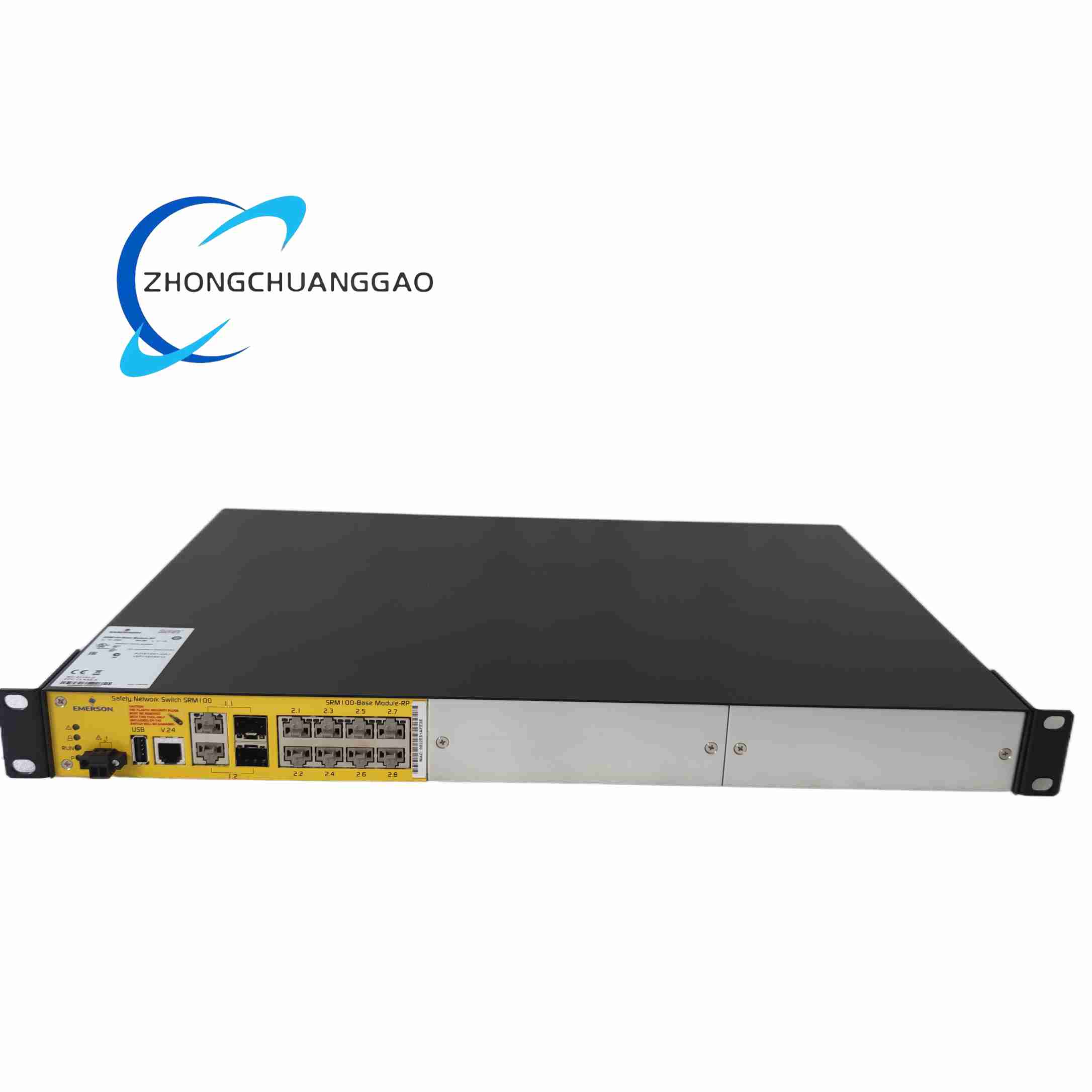
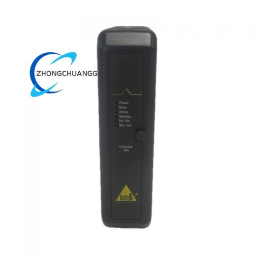
SS6048R2P3 is a high-density redundant analog output signal isolation module customized for Emerson DeltaV DCS control systems, dedicated to converting digital control signals output by DCS I/O cards into standard 4–20mA analog current signals to drive field actuators including control valves, variable frequency drive speed regulators and proportional regulating actuators. The suffix R2P3 indicates dual-channel redundant output design with three-stage surge protection circuit built-in.
Description
Core Technical Specifications
- Operating Power Input: 24 VDC industrial control power, maximum power consumption 45mA
- Output Channel Configuration: Two independent analog output channels, each channel equipped with dual redundant drive circuits
- Standard Output Signal Range: 4–20mA analog current signal, maximum load driving resistance 750Ω per channel
- Galvanic Isolation Parameter: 2500 VAC isolation voltage between DCS system side and field actuator side for each channel
- Surge Protection Grade: Three-stage composite surge suppression circuit, complies with IEC 61000-4-5, withstands 4kV lightning surge impact
- Output Signal Filtering: Built-in 3rd-order low-pass filter, fixed cutoff frequency 50Hz to suppress high-frequency switching noise from field frequency converters
- Redundant Switching Response Time: Less than 0.5ms bumpless transfer when single output circuit fails
- Overcurrent Protection Threshold: 25mA per channel, automatic current limiting and fault indication upon overcurrent
- Operating Ambient Temperature: -40°C ~ +70°C
- Storage Temperature Range: -45°C ~ +85°C
- Allowable Operating Altitude: Maximum 3000m above sea level; above 1000m ambient temperature derating 1°C per 100m elevation increase
- Mounting Standard: 35mm DIN rail compact mounting
- Overall Dimensions: 110mm height × 45mm width × 85mm depth
- Net Weight: 0.32kg
- Certifications: CE, UL, IEC 61508 SIL 2 functional safety certification, RoHS environmental compliance
Material Composition & Structural Features
- DIN Rail Enclosure: High-impact flame-retardant gray PA66 plastic housing, rear integrated spring DIN rail buckle supporting quick disassembly without tools
- Internal PCB Layout: Multi-layer high-Tg FR-4 flame retardant circuit board; each analog output channel’s dual redundant drive circuits are arranged with independent isolation barriers to avoid mutual circuit interference; all signal isolation and surge protection circuits are coated with transparent polyurethane conformal coating for moisture and corrosion resistance
- Core Electronic Components: Dual redundant low-drift digital-to-analog conversion chips per channel, high-voltage isolation transformers, low ESR tantalum filter capacitors, three-stage composite surge suppressors including TVS diodes, gas discharge tubes and varistors, high-precision current sampling resistors
- Wiring Terminal Design: Front-mounted dual-group spring push-in terminal blocks; one group for DCS I/O card connection (system side), one group for field actuator wiring (field side); each terminal engraved with channel number, positive/negative polarity and redundant circuit identification marks
- Multi-Color LED Diagnostic Indicators: Front panel integrated dedicated LED indicators for each channel: green LED for normal power supply, amber LED for single redundant circuit fault, red LED for channel overcurrent/short-circuit fault
- Internal Redundancy Mechanical & Circuit Interlock: Independent cross-monitoring signal lines between dual redundant drive circuits of each channel; hardware interlock logic prevents simultaneous disconnection of both redundant output circuits under any single point failure condition
Working Principle
- 24VDC control power energizes the module internal isolated power supply circuit, providing stable independent power for each channel’s dual redundant digital-to-analog conversion and signal drive circuits
- Digital control commands transmitted from Emerson DeltaV I/O analog output cards enter the system-side input terminals of the module, and are distributed to two parallel redundant signal conversion circuits of the corresponding channel
- Dual redundant digital-to-analog conversion chips simultaneously convert the received digital control values into identical 4–20mA analog current drive signals; cross-monitoring circuit continuously compares output current values of the two redundant circuits to detect signal deviation caused by single-circuit component failure
- The two groups of analog current signals pass through independent multi-stage low-pass filter circuits to filter out high-frequency electromagnetic interference noise generated by cabinet internal frequency converters and high-power contactors
- Filtered analog signals pass through high-voltage galvanic isolation transformers to achieve complete electrical isolation between DCS control system and field actuator wiring loops, blocking common-mode voltage and ground loop interference between cabinet and field equipment
- Two groups of isolated analog drive signals are output to field actuator terminals through redundant output circuits; dual-circuit parallel current sharing operation under normal working conditions, the two circuits jointly drive the field control valve or regulating actuator
- Single redundant circuit failure processing logic: If cross-monitoring circuit detects abnormal current deviation, open-circuit or short-circuit fault in one of the two redundant drive circuits, the faulty circuit is instantly cut off by hardware interlock switch; the intact redundant circuit independently bears full load current output, completing bumpless redundant switching within 0.5ms without actuator output fluctuation or control loss
- Channel overcurrent and short-circuit protection mechanism: Real-time current sampling resistors continuously monitor output current of each channel; once current exceeds 25mA threshold caused by field actuator wire short-circuit or actuator coil internal short-circuit, the module activates hardware current limiting protection, cuts off output drive signal, latches red fault LED alarm, and transmits fault diagnosis information to upper DeltaV DCS system
- Three-stage surge protection circuit absorbs instantaneous high-voltage lightning surge and power grid fluctuation surge transmitted from long-distance field wiring, preventing high voltage from breaking through isolation circuits and causing permanent damage to DeltaV core I/O analog output cards
Application Scenarios
- Emerson DeltaV DCS high-reliability control loops for petrochemical refining, ethylene and coal chemical production workshops (reactor temperature regulating valves, pipeline flow control valves)
- Thermal power plant boiler main steam pressure control valve, water supply flow regulating actuator signal drive
- Natural gas liquefaction plant, gas transmission station pressure regulating valve analog output control
- Municipal large-scale wastewater treatment plant aeration tank oxygen content proportional regulating actuator drive
- Pharmaceutical sterile batch production workshop precision flow control valve redundant signal output conditioning
Installation Requirements
- DIN Rail Mounting Specification: Vertically install SS6048R2P3 on standard 35mm top-hat DIN rail inside DCS control cabinet; fully lock rear elastic buckle to resist mechanical vibration generated by cabinet internal fans and contactors
- Redundant Channel Wiring Separation Rule: For each output channel’s dual redundant field wiring loops, use two independent shielded twisted-pair cables; strictly prohibit parallel wiring of two redundant circuits with a single cable, which will eliminate independent fault isolation capability of dual-circuit redundancy
- Wiring Cable Classification & Spacing: Separate system-side short-distance DCS I/O connecting wires and field-side long-distance actuator signal cables; maintain minimum 15cm spacing between analog output signal cables and cabinet internal three-phase high-current power cables, frequency converter output cables to avoid electromagnetic interference triggering redundant circuit false switching
- Spring Terminal Wiring Standard: Spring push-in terminals accept solid copper wire cross-section 0.5mm² ~ 1.5mm²; strip wire insulation length to 6–8mm, fully insert wire core into terminal hole and lock spring buckle tightly; stranded wires must be equipped with crimped wire ferrules before terminal wiring to prevent scattered wire strands causing short-circuit
- Equipotential Grounding Mandate: Connect module dedicated PE protective ground terminal to cabinet equipotential ground bus with copper ground wire cross-section ≥ 2.5mm²; single-point grounding mode is mandatory, multi-point grounding will generate ground loop potential difference and destroy redundant circuit cross-monitoring accuracy
- Cabinet Ventilation & Heat Dissipation Requirements: Maintain vertical air circulation gap of at least 20mm above and below the module on DIN rail installation row; do not install heat-generating power supply modules, servo drives or large-capacity relays directly adjacent to SS6048R2P3; avoid installing the module in cabinet closed corners without natural air convection
- Field Actuator Load Resistance Limit: Calculate total loop load resistance of field actuator coil and long-distance wiring before wiring; ensure total load resistance does not exceed the rated maximum 750Ω per channel; excessive load resistance will cause output current attenuation and inaccurate control valve positioning
Operation & Maintenance Precautions
- Pre-Power-On Wiring Inspection: Before supplying 24VDC control power to the module, fully inspect all field actuator wiring for short-circuit between positive and negative wires, cable insulation damage, terminal loose contact; field-side short-circuit will trigger channel overcurrent protection, repeated short-circuit impact will accelerate internal drive chip aging and permanent circuit damage
- Redundant Circuit Fault Inspection Cycle: Conduct quarterly maintenance inspection of each channel’s dual redundant circuit operating status via front panel amber fault LED; if amber fault indicator lights continuously for a single channel, cut off module power supply to inspect internal redundant drive circuit component damage or field redundant wire open-circuit fault
- Surge Protection Component Regular Maintenance: Conduct semi-annual disassembly inspection of module internal three-stage surge protection circuit; if gas discharge tubes show blackened discoloration after multiple lightning surge impacts, replace the entire module immediately to maintain long-distance field wiring lightning surge protection performance
- Redundant Fault Switching Test Operation: Conduct annual functional test of redundant switching performance; artificially disconnect one redundant field wire loop under normal operating power supply, observe field actuator output remains stable without jitter, front panel amber fault LED lights up normally; if actuator output fluctuates severely during switching, replace the faulty module
- Fault Alarm Reset Procedure: When red channel overcurrent fault LED lights up, first cut off module 24VDC power supply, troubleshoot field actuator coil short-circuit, wiring positive-negative short-circuit or excessive load resistance fault; after eliminating root failure cause, re-energize the module to automatically clear fault latch status and restore normal dual-circuit redundant output operation
- Spare Module Storage & Preservation Rules: Store spare SS6048R2P3 modules in temperature-controlled dry warehouse with ambient temperature range 10°C ~ 30°C and relative humidity ≤ 60%; seal spare modules with moisture-proof plastic film and place desiccant inside packaging to avoid long-term high-humidity storage causing conformal coating blistering and internal circuit corrosion
- High-Temperature Environment Continuous Operation Restriction: When control cabinet internal ambient temperature exceeds 60°C, reduce the number of adjacent heat-generating electronic modules to avoid module over-temperature operation; continuous long-term operation above 70°C will accelerate aging of internal tantalum filter capacitors and isolation transformers, reducing redundant circuit switching stability and service life
Reviews
There are no reviews yet.