
Product Short Description
Product Overview
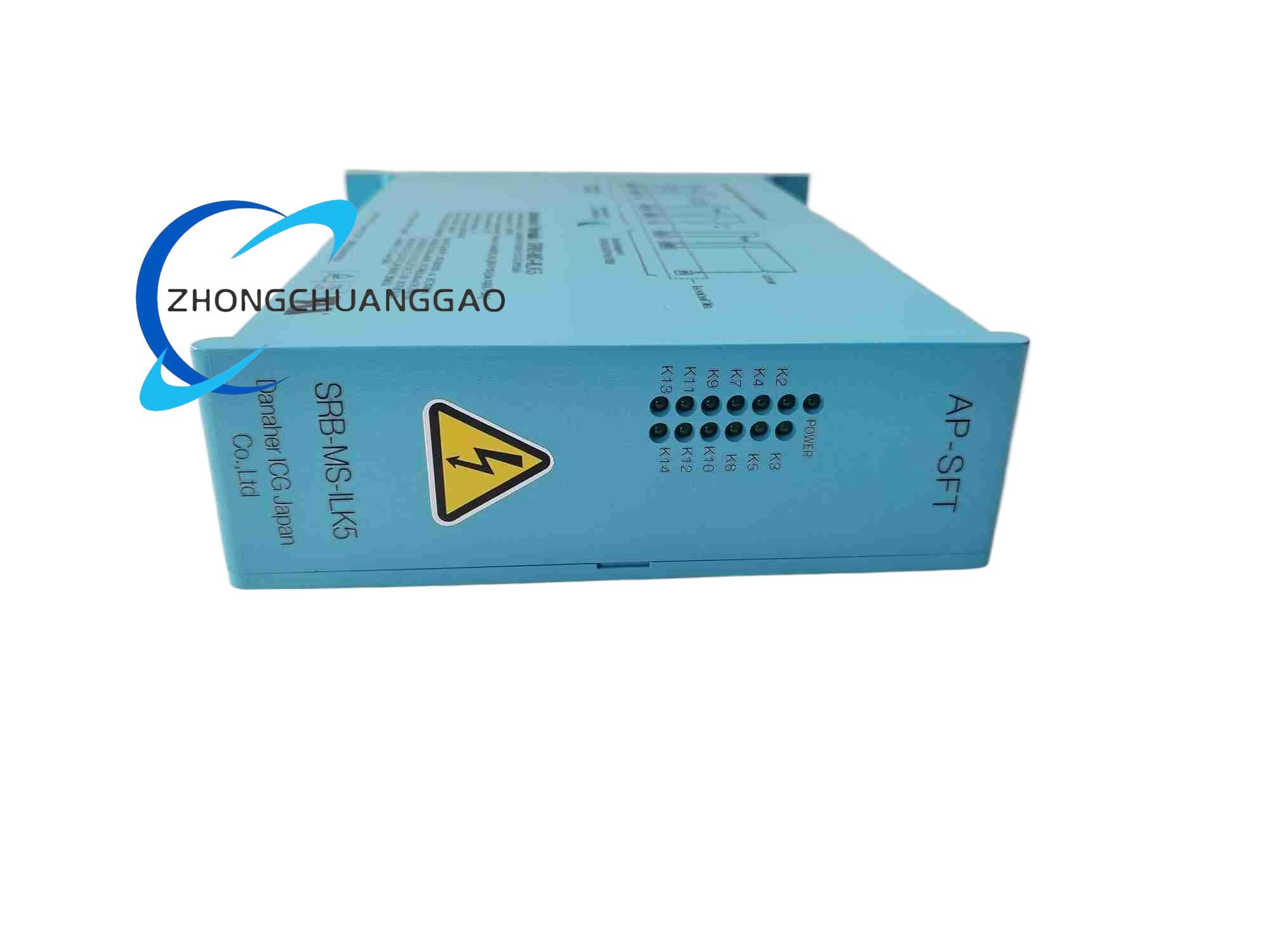
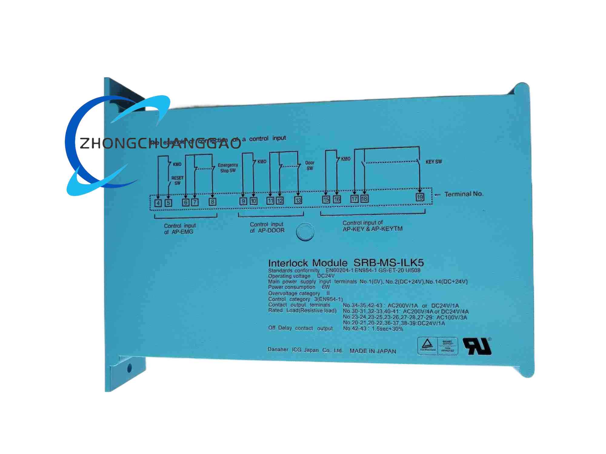
SRB-MS-ILK5 is a high-performance functional safety interlock module developed by Kollmorgen (Danaher Motion Group), specially designed for multi-axis servo motion control systems of automated machinery, machine tools and industrial robots. The core safety functions include Safe Torque Off (STO) drive power cutoff and secure overspeed monitoring, complying with ISO 13849-1 Category 4, Performance Level e (PL e) and IEC 61508 SIL 3 functional safety standards.
Description
Core Technical Specifications
- Module Operating Supply Voltage: 24 VDC industrial safety control power supply
- Safety Signal Input Channels: Dual-channel redundant digital safety input circuits (emergency stop button, safety guard door positive opening interlock switch, servo drive overspeed fault feedback signal)
- Safe Torque Off (STO) Output Interfaces: Multi-channel isolated STO enable/disable signal output terminals compatible with all Kollmorgen AKD series servo drives
- Speed Monitoring Threshold Range: Configurable overspeed trip threshold from 100 rpm to 10,000 rpm, independent dual-channel speed signal cross-verification to eliminate single signal circuit failure blind spot
- Functional Safety Certification Level: ISO 13849-1 Category 4 / PL e; IEC 61508 SIL 3; EN 62061 SIL CL 3
- Fault Diagnosis Logic: Built-in dual-channel input cross-short circuit fault detection, internal relay contact welding fault self-test, STO output circuit continuity self-diagnosis on each machine startup cycle
- Operating Ambient Temperature Range: -10°C ~ +60°C
- Shock & Vibration Resistance: IEC 60068-2-6 vibration test 10–1000Hz, 5g peak acceleration; IEC 60068-2-27 shock test 20g peak
- Enclosure Mounting Standard: Standard 35mm DIN rail mounting width, compact single-width DIN rail module size
- Net Weight: 0.42 kg
- Certifications: CE, UL functional safety certification, RoHS environmental compliance
Material Composition & Structural Features
- Outer DIN Rail Enclosure: High-strength flame-retardant light gray PA66 plastic injection molded housing, integrated rear side spring DIN rail clamping buckle for rapid installation and removal
- Internal Safety Circuit PCB: Double-sided FR-4 flame retardant circuit board with dual redundant isolated safety signal circuits separated by isolation barrier layout to avoid single circuit fault causing full safety function failure
- Safety Electronic Components: Dual independent safety control microprocessors for cross-verification of all safety signals, force-guided mechanical safety relay contact groups, optocoupler galvanic isolation chips, reverse polarity and surge protection TVS diodes
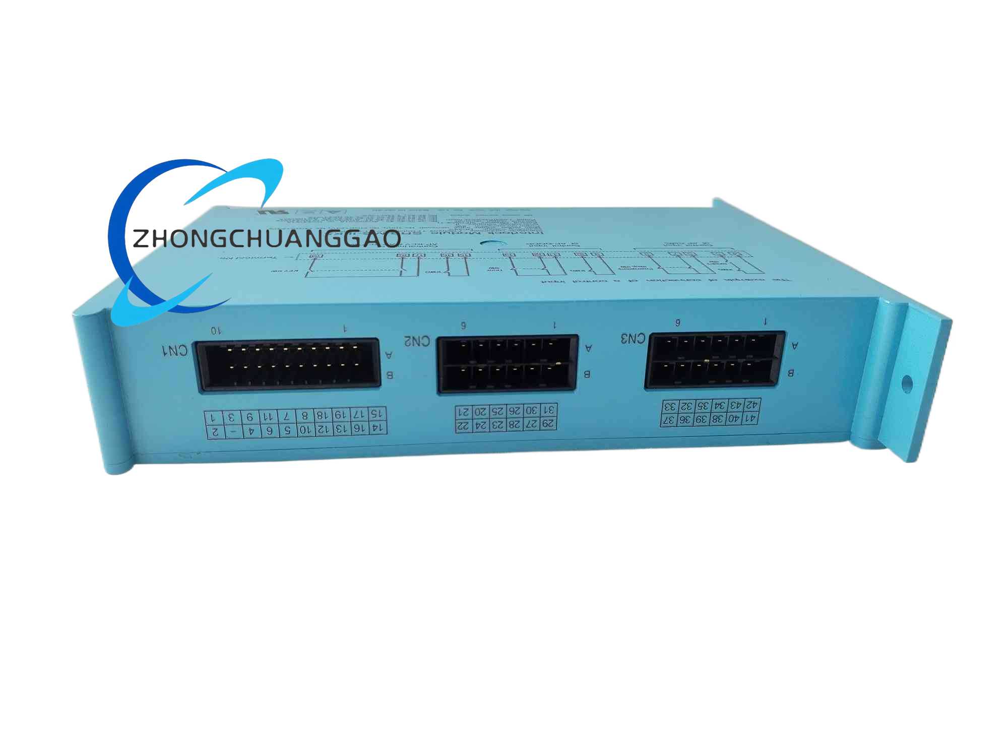
- Wiring Terminals: Front side spring pluggable terminal blocks with clearly printed terminal function labels (24VDC Power In, Ch1 Safety Input, Ch2 Safety Input, STO Output, Fault Signal Output)
- Diagnostic Indicator Interface: Front panel multi-color LED status indicators for Channel 1 Input Normal, Channel 2 Input Normal, STO Active Safety Stop, Internal Fault Detected, Overspeed Trip Active
- Internal Mechanical Safety Structure: Force-guided positive opening relay contact design compliant with EN 1088 safety switch standard; mechanical interlock between dual relay armatures to prevent simultaneous contact welding failure of both redundant channels
Working Principle
- 24VDC safety control power supply energizes the module dual redundant internal safety control circuits, completing full self-diagnosis cycle on power-on startup: testing dual input channel cross short-circuit fault, internal relay contact welding fault, STO output circuit continuity
- Dual independent safety input channels receive redundant digital signals from machine safety components: dual contact safety guard door interlock switches, dual-channel emergency stop pushbuttons, servo drive overspeed fault feedback signals; two input channel signals are continuously cross-compared by dual microprocessors
- Normal operating state: Both dual input channels maintain consistent closed-circuit safety signal state, internal dual safety relay contact groups remain closed, STO output terminals continuously send torque enable signal to all connected servo drives, servo motors can output normal torque for machine motion operation
- Safety interlock trigger state: Any single safety input channel signal state changes to open-circuit (safety door opened, emergency stop pressed, overspeed fault triggered); dual microprocessors detect input signal inconsistency, immediately cut off both dual safety relay coil power supply
- Force-guided safety relay contacts open simultaneously to terminate STO enable signal output to servo drives; servo drives activate Safe Torque Off safety function to rapidly demagnetize motor stator windings and eliminate all motor output mechanical torque within microsecond-level response time
- Overspeed monitoring independent logic continuously receives encoder speed feedback signals from connected servo axes, cross-verifies speed value via dual signal sampling circuits; if actual motor rotational speed exceeds preset overspeed threshold, the module independently triggers STO safety stop regardless of safety door/emergency stop input state
- Any detected internal circuit fault (cross-short input channel, relay contact welding, STO output open circuit) latches the module into permanent safety stop state, lights red fault LED indicator and outputs dry contact fault alarm signal to upper machine PLC for fault record and operator alarm prompt; fault latch state can only be reset by full module 24VDC power supply cutoff and re-energization after eliminating root fault cause
Application Scenarios
- CNC machining center, vertical machining center multi-axis servo drive safety interlock and STO torque cutoff control
- Automated assembly robots, delta parallel robots, SCARA robots safety guard door and emergency stop safety control
- Packaging high-speed automatic machinery, printing rotary press servo motion system functional safety monitoring
- Metal stamping automated production lines, hydraulic press auxiliary servo axes safety interlock protection
- Automated warehouse stacker cranes, logistics sorting robot overspeed safety stop control
Installation Requirements
- DIN Rail Mounting Standard: Install the SRB-MS-ILK5 module vertically on standard 35mm top hat DIN rail inside machine electrical control cabinet; slide rear spring clamping buckle fully locked onto DIN rail to prevent vibration-induced module loosening during machine high-speed operation
- Safety Wiring Redundancy Rule: All safety input signal wiring (emergency stop, safety door interlock) must adopt dual independent cable loops connected to Channel 1 and Channel 2 input terminals respectively; strictly prohibit single-wire parallel connection to both input channels, which will eliminate dual-channel redundant fault detection capability
- Terminal Wiring Torque Standard: Spring terminal block wire clamping screws tightened to 0.7 N·m; safety signal wiring uses shielded twisted pair cable with single-end shield grounding at control cabinet PE ground bus
- Power Supply Isolation Requirement: The module 24VDC safety control power supply must use an independent safety-grade isolated DC power supply, shared power supply with servo drive main power circuit is prohibited to avoid power supply noise interference distorting safety input signal accuracy
- STO Output Wiring Compatibility: Connect STO output terminals to each servo drive STO enable signal input via independent shielded signal cables; maintain minimum 15cm wiring separation between STO signal cables and servo drive high-power three-phase motor cables to eliminate electromagnetic interference triggering false STO safety stop
- Cabinet Ventilation Clearance: Maintain minimum 20mm vertical air circulation gap above and below the module on DIN rail installation row; avoid installing adjacent to high-temperature heat-generating components such as servo drives, power supply modules
Operation & Maintenance Precautions
- Machine Startup Self-Diagnosis Rule: After powering on the machine control cabinet, wait for the module to complete full startup self-diagnosis cycle (approximately 3 seconds); if red fault LED remains lit after self-diagnosis completion, prohibit machine motion axis jogging or automatic cycle startup, troubleshoot fault root cause first
- Dual Redundancy Wiring Inspection: Conduct quarterly wiring inspection of all dual-channel safety input cables; check for cable insulation cracking, wire strand breakage, terminal loose contact; single channel open circuit hidden danger will lead to loss of dual cross-verification safety protection capability
- Force-Guided Relay Contact Lifespan Monitoring: Internal mechanical safety relay contact groups have rated mechanical service life of 100,000 safety interlock trigger cycles; record cumulative safety stop trigger count on machine maintenance log, replace the entire module after reaching rated cycle count to avoid contact welding safety failure risk
- Overspeed Threshold Parameter Setting Restriction: The preset overspeed trip threshold must be set 10–15% higher than the maximum normal operating speed of the corresponding servo motor axis; threshold set too close to normal operating speed will trigger frequent false overspeed safety stops and disrupt normal machine production operation
Reviews
There are no reviews yet.