
Product Short Description
Product Overview
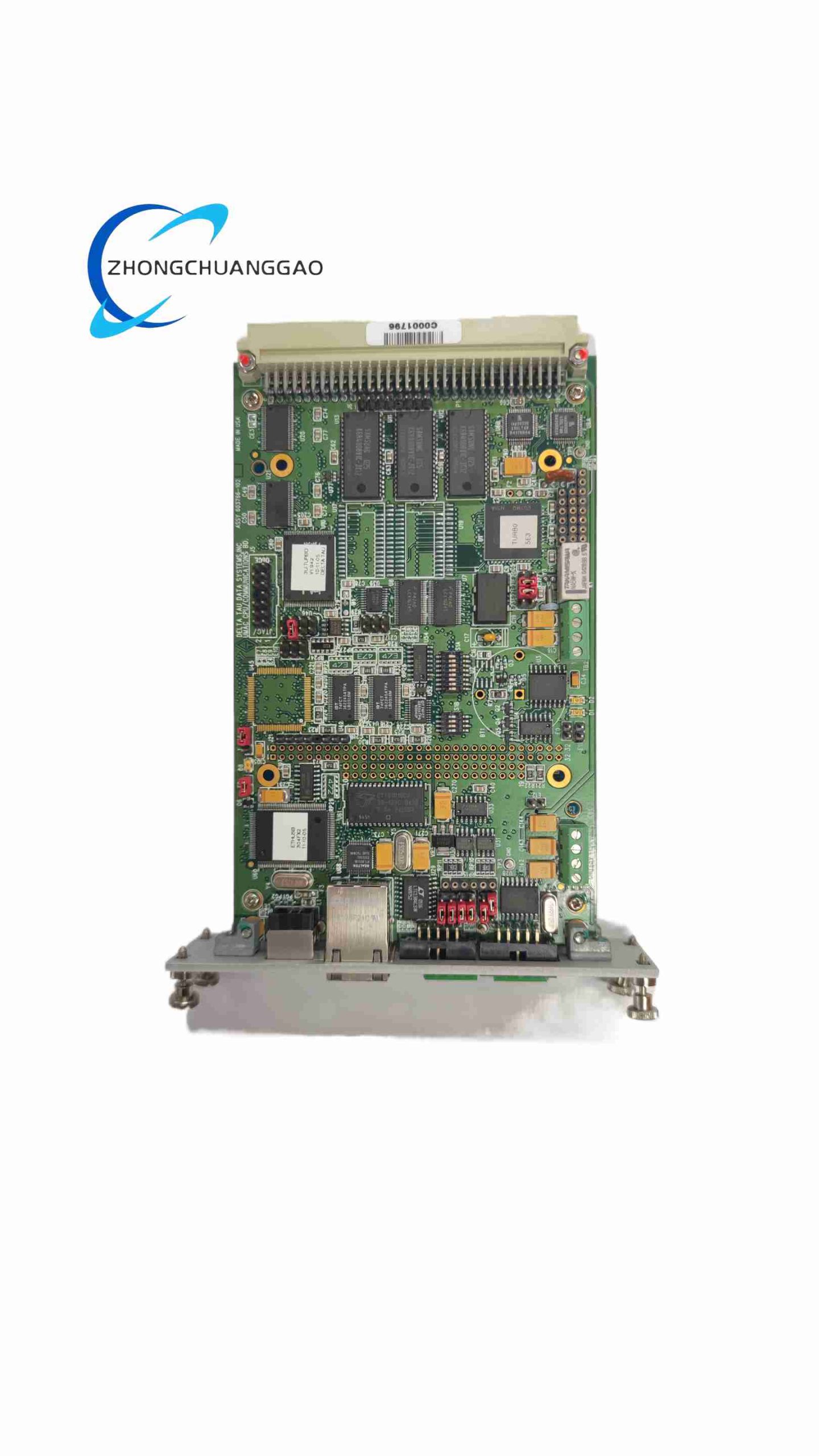
The PMAC2 CPU is a dedicated high-performance motion control core module manufactured by Delta Tau, now under Omron Automation product line. It serves as the central computing unit for the full PMAC2 series programmable multi-axis motion controllers, undertaking all high-speed real-time servo closed-loop control, multi-axis trajectory interpolation, PLC sequential logic operation and multi-channel industrial communication data exchange tasks simultaneously.
Description
Motion Control Core Capabilities
Supports synchronous coordinated motion control of multiple independent servo axes
Three-layer closed-loop servo control algorithm built-in: position loop, velocity loop, torque loop adjustable PID servo parameters
Complete standard motion function set: linear interpolation, circular arc interpolation, continuous contour path following, master-slave electronic gearing, rotary electronic cam curve tracking, high-speed position trigger registration capture, single-axis jogging, homing reference return operation
Onboard embedded dedicated real-time motion control firmware, independent of general operating system, microsecond-level high-speed control cycle
Two parallel executable program systems supported: dedicated PMAC motion command programming language for motion trajectory programming, ladder diagram PLC sequential logic program for equipment interlock, fault alarm and auxiliary mechanical action automatic control
Built-in multi-level independent memory partitions: motion program storage memory, real-time motion variable buffer memory, trajectory pre-cache memory, fault log recording memory
Standard onboard RS232 serial communication port for PC offline programming and parameter downloading
Expandable industrial Ethernet communication module interface for high-speed real-time data exchange with upper HMI and host computer
Support analog ±10V servo output interface for analog servo drives, digital fieldbus expansion interface compatible with digital servo bus drives
Expandable digital input/output terminal modules, analog input/output signal acquisition expansion boards
Module installation method: Standard industrial electrical cabinet rack mounting or panel embedded mounting
Continuous operating ambient temperature range: 0°C ~ +50°C
Storage temperature range with power disconnected: -20°C ~ +70°C
Adaptive relative humidity range: 5% ~ 95% non-condensing industrial cabinet environment
Supporting PC-side configuration software: Official PMAC2 motion development software, integrating motion program editor, servo PID auto-tuning tool, real-time motion curve monitoring display, equipment fault code recording and diagnostic analysis function modules
-
High-Speed Real-Time Multi-Axis Motion Trajectory Planning & Servo Control
Ultra-short microsecond-level servo closed-loop control cycle, real-time reading of motor encoder position feedback signals, automatic calculation of position, velocity and torque adjustment output values through configurable PID servo algorithms, realizing stable low-following-error high-precision axis positioning and multi-axis synchronous contour machining motion.
-
Comprehensive Advanced Motion Control Functional Library
Built-in complete set of industry-standard advanced motion functions to meet complex automation equipment motion requirements: multi-axis continuous synchronous contour cutting for CNC machine tools, electronic gear ratio synchronization for printing rotary roller equipment, electronic cam curve following for high-speed packaging filling equipment, high-speed product position registration capture for automated testing sorting equipment.
-
Integrated Independent PLC Sequential Logic Control
Parallel operation of PLC logic programs independent of high-speed motion control cycles, responsible for processing all equipment auxiliary interlock logic: travel limit switch signal detection, emergency stop safety circuit interlock, solenoid valve and air cylinder auxiliary mechanical action automatic control, equipment operation fault judgment and alarm signal output. No external independent PLC hardware is required for complete equipment logic control.
-
Flexible Multi-Type Servo Drive Compatibility
Dual servo output modes supported without hardware modification: analog ±10V voltage signal output compatible with all mainstream analog servo and stepper drives; digital fieldbus communication expansion module access to digital bus servo drives, realizing high-speed digital encoder feedback and multi-axis synchronous digital motion control.
-
Expandable Digital & Analog Signal I/O System
Modular expandable I/O hardware architecture, users can freely add digital input/output expansion boards for limit switches, proximity sensors, indicator lights and actuators, as well as analog signal acquisition expansion modules for pressure, temperature, flow analog transmitters, to match different equipment signal detection and actuation point quantity demands.
-
Multi-Channel Industrial Communication Data Exchange
Multiple communication channels can work simultaneously: serial port offline program downloading and equipment debugging, industrial Ethernet real-time bidirectional data exchange with touch screen HMI and upper SCADA monitoring host computer, realizing real-time equipment motion state data uploading and remote motion command downloading from upper monitoring systems.
-
Built-In Full-Range Real-Time Fault Monitoring & Recording System
Continuous real-time monitoring of all motion axis operating states during equipment automatic operation: motion following error over-limit, servo drive fault feedback signal, positive/negative travel hard limit trigger, emergency stop circuit disconnection, motion program execution abnormal faults. Once any fault condition is triggered, the CPU immediately executes preset safety stop motion logic, locks servo output signals, outputs fault alarm signals to external indicator lights and stores complete fault codes, fault occurrence timestamps and corresponding axis motion state data into internal fault log memory for post-failure maintenance troubleshooting analysis.
-
Modular Hardware Expansion Architecture
The PMAC2 CPU main control module supports flexible addition of various function expansion hardware boards without replacing the main CPU module: multi-axis servo axis expansion cards, industrial communication bus expansion modules, digital/analog I/O expansion boards, pulse encoder signal expansion acquisition boards, adapting to equipment upgrade expansion requirements of increased motion axes or more signal detection points.
- Outer Module Housing Structure
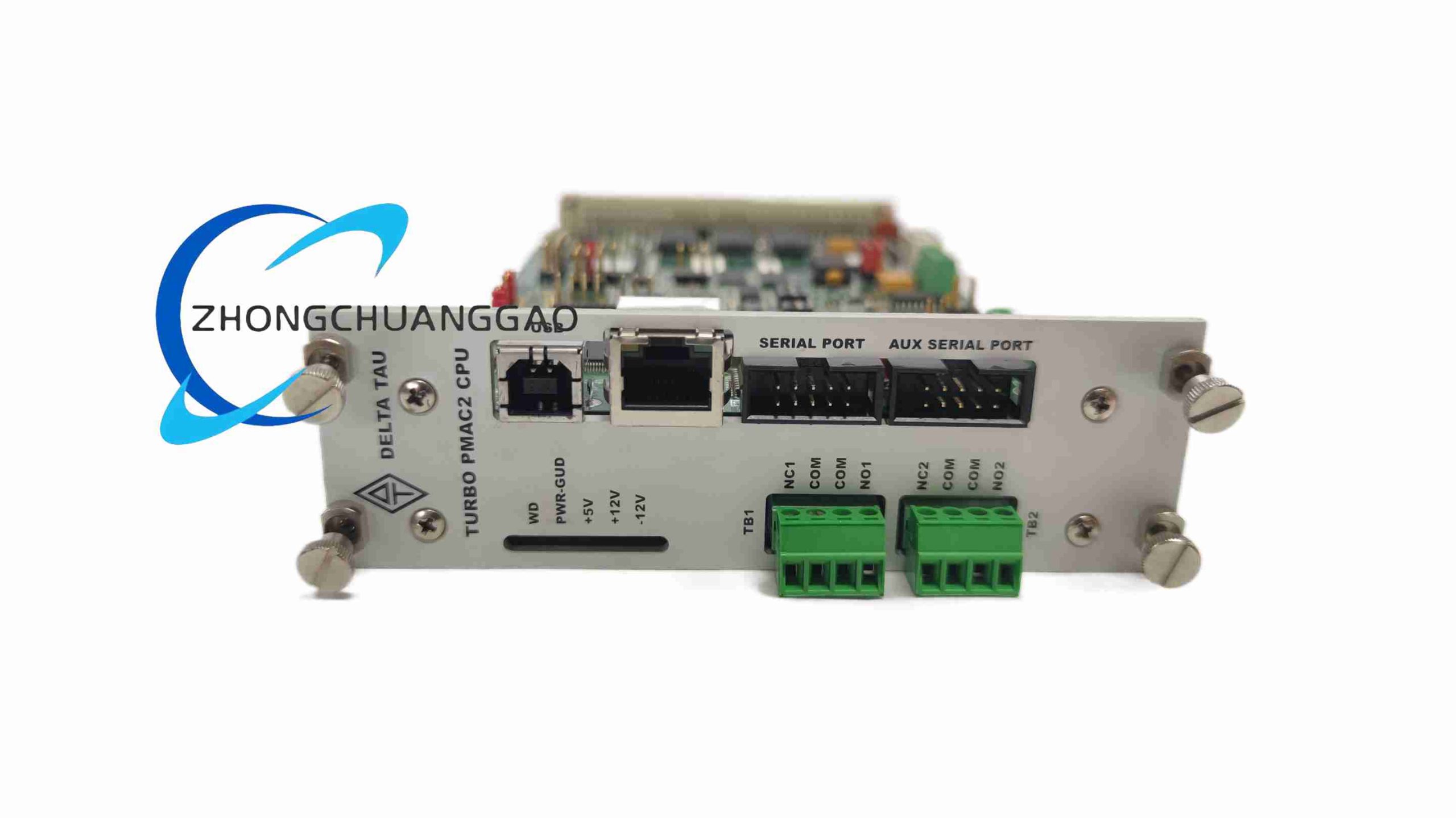
Integrated cold-rolled steel alloy metal shielding shell for the PMAC2 CPU main module, the metal shell serves as both mechanical protection frame for internal circuit boards and electromagnetic shielding barrier, blocking external industrial high-power motor electromagnetic interference signals from disturbing internal motion control high-speed processor operation. The front panel of the metal shell is equipped with printed text marking for each communication port, I/O expansion slot and status indicator lights, facilitating on-site maintenance personnel rapid interface identification.
- Internal Core Circuit Board Hardware Composition
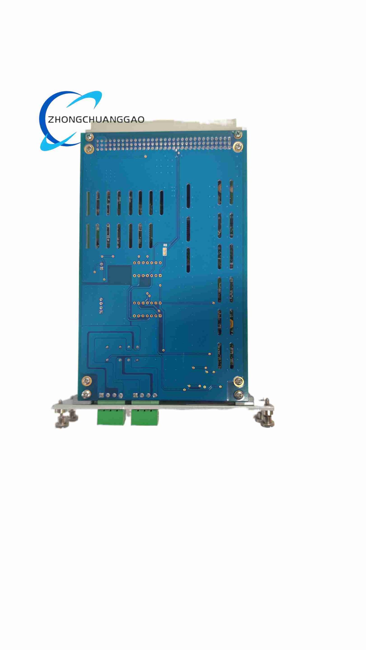
Multi-layer high-density industrial FR4 printed circuit board carries all core computing hardware components: high-speed dedicated motion control processor chip, large-capacity flash memory chip for motion program and parameter storage, multi-channel encoder signal differential receiving circuits, analog servo output operational amplifier circuits, serial and Ethernet communication transceiver chips, multi-channel fault signal detection logic circuits. All high-speed digital circuits and low-noise analog circuits are separated by internal ground shielding traces on the PCB to eliminate mutual signal crosstalk interference.
- Front Panel Status Indicator Light Layout
Independent group LED status indicator lights arranged on the module front panel: main power supply operating indicator, motion program running indicator, servo axis fault alarm indicator, communication port data transceiving activity indicator, emergency stop safety circuit trigger indicator. Maintenance personnel can directly judge the real-time equipment motion control operating state and fault type through the indicator light display without connecting PC configuration software.
- Terminal Wiring Interface Structure
Detachable screw-type insulated wiring terminal blocks for digital I/O signals, analog servo output signals and power supply input wiring. All terminal blocks are marked with clear signal function text labels, supporting quick disassembly wiring operation without removing the entire CPU module from the equipment rack, simplifying on-site equipment wiring maintenance and hardware replacement work.
-
Power-On Hardware Self-Test & System Initialization Stage
After the PMAC2 CPU module is connected to 24VDC industrial control power supply and powered on, the onboard dedicated motion control processor automatically executes full-system hardware self-inspection sequence: sequentially detecting communication port transceiver circuits, all encoder signal input channels, analog servo output circuits, digital I/O signal acquisition channels, internal program storage flash memory chip and expansion hardware slot connection status. After completing full hardware function self-test without fault codes, the processor loads all pre-stored motion programs, servo PID tuning parameters, PLC logic programs and equipment safety interlock configuration data from internal flash memory into real-time operating memory, then enters standby ready operation state, waiting for motion execution commands sent from HMI touch screen or PC host computer.
-
Multi-Source Signal Real-Time Acquisition & Preprocessing Stage
During normal equipment automatic operation, the CPU continuously collects three major categories of real-time signal data through multiple independent parallel signal acquisition channels:
- Axis motion feedback signals: High-speed differential encoder position feedback signals transmitted from each servo motor encoder are received and decoded by dedicated encoder signal circuits, converted into real-time axis actual position, velocity and acceleration numerical data, sent to the real-time servo control calculation loop with microsecond-level ultra-low transmission delay.
- Digital & analog field I/O signals: Digital signals from travel limit switches, emergency stop buttons, proximity sensors and equipment auxiliary actuators, as well as analog voltage/current signals from pressure, temperature and flow transmitters are continuously scanned and sampled by multi-channel I/O acquisition circuits, filtered to eliminate industrial field electromagnetic interference noise, then transmitted to the PLC sequential logic operation processing channel.
- Upper system communication command signals: Motion trajectory execution commands, parameter modification instructions and equipment operation control commands transmitted from touch screen HMI or upper industrial host computer through serial/Ethernet communication ports are received, data frame integrity verified via built-in CRC check logic, valid control commands are parsed and sent to the motion trajectory planning processing channel.
-
Hierarchical Dual Parallel Calculation Pipeline: Motion Servo Control & PLC Logic Processing
Two completely independent parallel real-time calculation pipelines operate simultaneously inside the CPU processor, separating high-priority hard real-time motion control tasks and low-priority sequential logic processing tasks to eliminate computing resource scheduling conflicts and guarantee ultra-stable motion control cycle timing accuracy:
-
Hard Real-Time Motion Servo Calculation Pipeline (Highest Priority Microsecond Control Cycle)
The dedicated motion control processor continuously runs high-frequency closed-loop servo calculation cycles. The pipeline receives real-time axis actual position feedback data from encoder circuits and target position coordinate data generated by the trajectory interpolation planning module, calculates position deviation (motion following error) between actual and target positions, then executes user-configurable PID position-velocity-torque three-layer servo control algorithms to generate real-time analog voltage or digital bus servo drive output control signals, transmitted to each servo drive to drive motor rotation. Simultaneously, the pipeline dynamically adjusts multi-axis synchronous motion target coordinate values according to electronic gearing, electronic cam and contour interpolation motion logic to realize coordinated multi-axis synchronous movement, and continuously monitors motion following error magnitude to judge axis motion over-limit fault conditions and trigger safety stop logic when fault thresholds are exceeded.
-
Sequential PLC Logic Calculation Pipeline (Background Parallel Cyclic Operation)
Parallel to the high-speed servo control pipeline, the CPU continuously cycles through the user-written PLC ladder logic program. The pipeline reads real-time digital and analog I/O field signal sampling data, executes sequential logic judgment, interlock condition comparison and auxiliary action timing control operations, outputs corresponding digital signal control values to drive solenoid valves, indicator lights and air cylinder actuators, judges equipment fault signal conditions and outputs fault alarm trigger signals to external alarm hardware, and synchronizes equipment operating state signal data to the upper HMI/SCADA monitoring system through communication ports.
-
Continuous Cyclic Operation & Multi-Layer Safety Fault Response Logic
The dual parallel calculation pipeline cyclic operation sequence runs uninterrupted for the full equipment automatic operation runtime. Built-in multi-layer safety protection monitoring logic continuously tracks three core equipment operating indicators in real time: each servo axis motion following error value, servo drive fault feedback signals, emergency stop and travel limit safety circuit state.
Once abnormal fault conditions are detected in any monitoring item, the CPU immediately executes multi-stage safety protection response logic in fixed priority order: first cut off all servo drive output control signals to stop all motor axis movement; second lock all new motion trajectory program execution commands; third output continuous fault alarm digital signal to external alarm light and buzzer hardware; fourth record complete fault code, fault occurrence timestamp and corresponding axis motion state data into internal fault log memory for later maintenance troubleshooting analysis. After maintenance personnel eliminate the root cause of the equipment fault and manually reset the fault state through the HMI touch screen or front panel reset button, the CPU clears the fault lockout state and resumes normal standby motion control operation.
- Rack Mechanical Installation Standard Specifications
The PMAC2 CPU main control module must be horizontally installed on standard industrial electrical cabinet internal metal equipment mounting racks; vertical upside-down installation or inclined side tilt mounting is strictly prohibited, which will block internal circuit board natural air convection heat dissipation airflow and cause internal high-speed processor over-temperature operation instability and crash faults.
Reserve minimum 25mm empty vertical clearance space above and below the CPU module rack mounting position to ensure unobstructed natural heat dissipation airflow circulation. Do not install high heat-generating industrial components such as AC contactor banks, high-power servo drive power stages and large switching power supply modules within a horizontal distance of 12cm from the PMAC2 CPU module, to avoid external high-temperature thermal radiation superimposing internal CPU heat load and aggravating over-temperature risks.
All detachable wiring terminal blocks on the module front panel can be removed and wired before rack installation, and re-installed to the module after wiring completion, eliminating the need to disassemble the entire CPU module from the rack for wiring maintenance and hardware replacement work.
- Electrical Wiring Installation Standard Specifications
Power supply wiring requirements: Use shielded twisted pair copper wire for 24VDC control power input wiring, wire cross-section specification 0.75mm² ~ 1.5mm². The CPU module metal shielding housing must be reliably connected to the electrical cabinet main protective earth ground bus bar with dedicated short thick ground wire, to suppress industrial field high-power motor and inverter equipment electromagnetic interference signals from disturbing internal motion control high-speed processor stable operation.
Encoder and analog servo signal wiring requirements: All servo motor encoder feedback cables and analog ±10V servo output signal cables must adopt double-layer fully shielded twisted pair dedicated motion control signal cables. The metal shielding layer at both ends of each signal cable must be connected to cabinet protective earth ground, to eliminate differential signal electromagnetic interference and prevent distorted encoder position feedback data leading to motion positioning deviation faults.
Communication cable wiring requirements: Serial port programming debugging cables and industrial Ethernet communication cables connecting to HMI touch screen and upper host computer must use CAT5e fully shielded twisted pair Ethernet cables, separate communication signal cable wiring layout from high-power motor drive power cables inside the electrical cabinet, do not bundle communication cables and high-power power cables together to avoid cross-channel voltage coupling interference causing communication data frame loss and disconnection faults.
Digital I/O field signal wiring requirements: Digital input/output wiring for limit switches, emergency stop buttons, solenoid valves and proximity sensors uses standard insulated single-strand copper wire. Separate low-voltage digital signal wiring and high-voltage power wiring layout, maintain sufficient safety insulation distance between low-voltage signal terminals and high-voltage power terminals on cabinet terminal strips to prevent high-voltage creepage short-circuit hazards.
- Environmental Installation Restrictions
The PMAC2 CPU module and all matched servo drive, I/O expansion hardware must be installed inside fully sealed dust-proof industrial electrical control cabinets with rubber sealing door strips. Open cabinet installation exposed to factory workshop metal cutting dust, machine tool oil mist, corrosive acid/alkali chemical gas and direct water splashing is strictly prohibited. These contaminants will penetrate into the CPU module internal circuit board through ventilation gaps, corrode circuit board solder joints and integrated chip pin contacts, leading to permanent motion control hardware failure and equipment production line shutdown losses.
Avoid installing the CPU module rack mounting position directly facing the cooling fan exhaust air outlet of adjacent servo drive power modules; high-speed exhaust airflow carrying suspended dust particles will continuously accumulate on the module front panel wiring terminals and internal ventilation heat dissipation gaps, blocking natural heat dissipation airflow circulation and gradually increasing internal CPU operating temperature during long-term continuous equipment operation.
- CNC Machine Tools & Precision Machining Equipment
Vertical machining centers, horizontal lathes, multi-axis milling machines, metal engraving and woodworking CNC equipment; realizes multi-axis synchronous contour cutting, high-speed spindle motion control and automatic tool change auxiliary mechanical action logic control.
- Multi-Axis Automated Gantry Robots & Assembly Workstations
3-axis/5-axis linear gantry handling robots, automated electronic component assembly workstations, automotive parts precision pressing and fitting equipment; completes multi-axis synchronous material handling, positioning pressing and automatic product assembly motion control.
- Packaging, Printing & Converting High-Speed Production Machinery
High-speed filling and capping packaging machines, rotary label printing equipment, film slitting and rewinding converting machinery; uses electronic gearing and electronic cam motion functions to realize synchronous roller rotation, fixed-length material cutting and high-speed product positioning filling motion control.
- Semiconductor Wafer Processing & Precision Inspection Automation Equipment
Wafer sorting and conveying robots, chip testing automatic loading and unloading equipment, optical precision dimension inspection automation stations; realizes ultra-low vibration high-precision positioning motion control and real-time inspection data synchronous uploading to upper monitoring systems.
- Laser Processing Industrial Equipment
Laser cutting machines, laser marking equipment, laser welding automation workstations; completes two-axis/three-axis synchronous high-speed laser scanning contour motion control, real-time laser power output synchronous linkage with axis movement velocity.
- Intelligent Logistics Automated Sorting & Conveying Equipment
Large warehouse automatic sorting conveyor belts, palletizing robotic arms, AGV automatic loading and unloading auxiliary positioning equipment; realizes multi-station synchronous conveying speed coordination and pallet stacking coordinated multi-axis motion control.
-
Pre-Production Equipment Commissioning Mandatory Rules
Complete all equipment configuration programming work via official PMAC2 PC-side development software before powering the CPU module and connected servo drive hardware online: including all motion trajectory programs, multi-axis servo PID tuning parameter sets, PLC ladder logic interlock programs, digital/analog I/O signal allocation mapping tables and upper HMI communication data exchange parameter settings. Never modify core motion programs, servo PID parameters or safety interlock PLC logic while the production line equipment is running in automatic operation mode; real-time parameter modification during operation will trigger instantaneous servo output signal fluctuation, leading to axis motion jitter, product processing dimensional deviation or emergency equipment shutdown production interruption losses.
When configuring multi-axis coordinated motion electronic gearing, electronic cam and contour interpolation functions, strictly match data type, coordinate byte length and axis memory offset parameters between each motion axis; mismatched numerical data configuration will generate distorted motion target coordinate values, causing abnormal axis vibration, motion positioning deviation and product processing scrapping faults.
After completing all wiring installation work, carry out full equipment offline safety function testing before enabling automatic production operation: manually trigger positive/negative travel limit switches and emergency stop buttons one by one to verify the CPU module can immediately cut off servo motor output and lock motion program execution, confirm all safety interlock protection functions work normally to eliminate personnel mechanical injury and equipment collision damage hidden dangers.
Carry out servo auto-tuning operation for each independent motion axis after wiring and offline safety testing are completed before formal production equipment operation. Adjust PID servo proportional/integral/derivative parameters according to actual mechanical load characteristics of each axis to eliminate axis motion vibration, overshoot positioning impact and excessive motion following error problems during high-speed movement operation.
-
Daily Continuous Equipment Operation Environmental & Power Cycle Restrictions
The CPU module must remain installed inside fully sealed dust-proof electrical control cabinets with closed cabinet doors during all production automatic operation periods; opening cabinet doors for long-term operation will lead to dust and oil mist contamination of internal circuit hardware and accelerated hardware failure risks.
Minimize frequent repeated power cycle operation of the entire equipment control cabinet power supply (including the PMAC2 CPU module); each full equipment power-off shutdown waiting interval must last minimum 45 seconds before re-powering the control cabinet. This waiting period allows all internal large-capacity power supply filter capacitors inside the CPU module and servo drive hardware to fully discharge, preventing instantaneous power-on voltage surge impact from damaging the CPU internal high-speed motion control processor chip and flash memory program storage chip, which will cause program file corruption and equipment motion control function loss.
-
Periodic Routine Maintenance & Standard Troubleshooting Guidelines
Semi-annual comprehensive equipment control cabinet maintenance cycle rules: Every six months of continuous production line equipment operation, carry out full dust cleaning maintenance for the PMAC2 CPU module and all matched servo drive and I/O expansion hardware. Use dry low-pressure compressed air with air pressure strictly controlled below 0.3MPa to blow accumulated dust off the module front panel wiring terminal blocks, ventilation heat dissipation gaps and internal rack-mounted hardware surfaces. Strictly prohibit using alcohol, acetone, thinner, water or any liquid chemical cleaning agents to wipe the CPU module metal housing, front panel indicator lights and wiring terminal blocks; liquid solvents will corrode plastic terminal insulation materials, metal conductive contact tin coating layers and circuit board protective solder mask coating, accelerating terminal oxidation and circuit board solder joint corrosion failure.
Configuration file backup update rule: Every time maintenance personnel modify any motion program, servo PID tuning parameters, PLC interlock logic or communication exchange parameter settings on production equipment, immediately connect the PC development software to export and save a complete full equipment configuration backup file. Store at least one offline backup copy of the latest complete configuration file in the workshop equipment maintenance computer hard disk, and reserve a spare USB flash drive storage backup copy on-site at each production line control cabinet for emergency rapid CPU module hardware replacement and configuration file recovery work when the original CPU module fails and needs to be replaced.
Standardized step-by-step fault troubleshooting process when module fault indicator light flashes red during equipment operation:
Step 1: Inspect the 24VDC control power supply input voltage stability first, check front panel power wiring terminal blocks for
loose contact, oxidation or short-circuit hidden danger, replace aging power cables if voltage fluctuates abnormally.Step 2: Check all servo encoder cables, analog signal lines and Ethernet communication cables for insulation cracking, connector loosening, poor shielding grounding, re-plug all connectors firmly and re-tighten shielding ground terminals.
Step 3: Connect the PMAC2 official configuration software to download internal fault log records, read fault codes and timestamp information to accurately locate the root cause of communication interruption, servo overload, following error over-limit or safety interlock trigger failure.
-
Software Version & Document Management Requirements
Keep the firmware version of the PMAC2 CPU module consistent with the matching PC-side development software version; mismatched versions will lead to abnormal communication, motion program parsing errors and servo parameter loss problems.
All motion programs, PLC ladder logic, servo tuning parameters, I/O mapping tables and equipment wiring schematics shall be filed and archived uniformly, record all customized motion algorithms, axis calibration parameters and equipment special control logic for subsequent equipment maintenance, module replacement and equipment transformation upgrade work.
-
Long-Term Storage Spare Module Preservation Rules
Spare unused PMAC2 CPU control modules shall be stored in constant-temperature, dry, ESD anti-static warehouse environment, the storage temperature range shall be controlled between -10°C ~ +40°C, avoid long-term storage in high humidity, high temperature, dust and corrosive gas environment, prevent internal circuit board moisture absorption insulation degradation, chip pin oxidation corrosion, so as to ensure normal function after rack installation and power-on.
-
Reviews
There are no reviews yet.