
Product Short Description
Product Overview
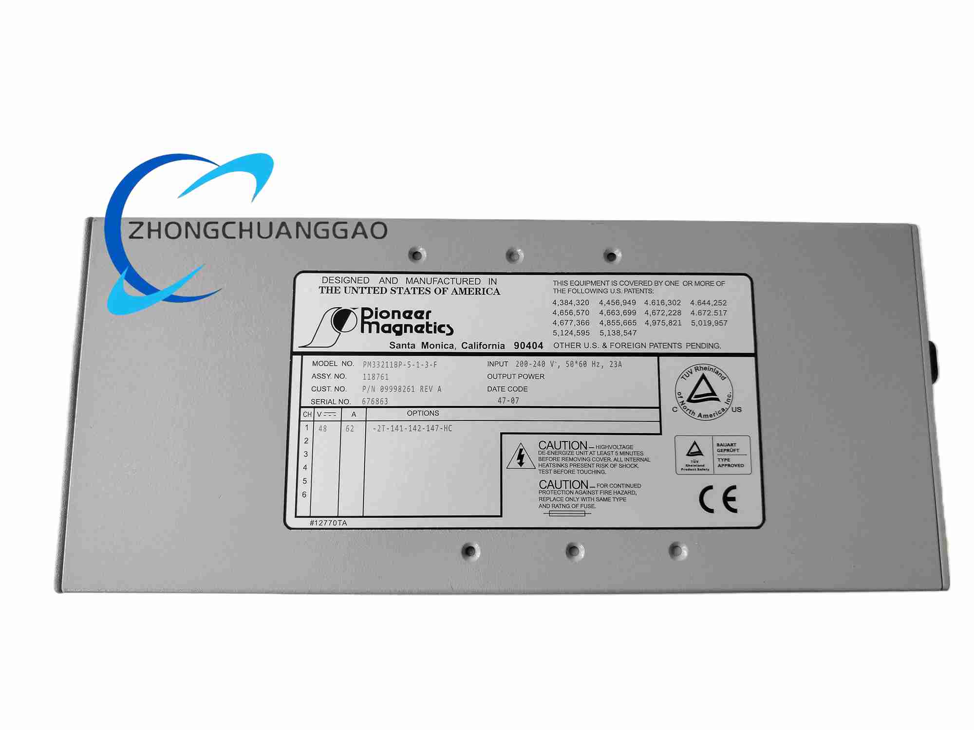
The PM33211BP-5-1-3-F is a compact low-profile planar magnetic component manufactured by Pioneer Magnetics, designed for medium-power isolated AC-DC and DC-DC industrial power conversion modules. The suffix codes define fixed winding structure and insulation grade: 5 turns primary single strand wire, 3 groups secondary laminated copper foil windings, F class enhanced high-temperature insulation encapsulation.
Description
Input & Winding Electrical Parameters
Primary winding rated input voltage range: 100VAC ~ 264VAC universal single-phase AC
Primary winding fixed turns: 5 turns single-strand high-temperature enameled copper wire
Secondary winding fixed configuration: 3 parallel laminated copper foil winding groups
Nominal output transformation ratio fixed by factory winding layout
Operating switching frequency range: 50kHz ~ 200kHz high-frequency SMPS circuit compatible
Continuous rated output power: 60W medium-power load capacity
Continuous secondary winding rated output current: 5A
Output winding DC resistance strictly controlled within low resistance tolerance to minimize power loss
Line and load voltage fluctuation suppression optimized for small compact power supply feedback control loops
Primary-secondary winding isolation withstand voltage: 2000VAC, continuous 1 minute without breakdown, leakage current ≤0.8mA
Internal winding insulation grade: Class F high-temperature resistant insulation material, maximum sustainable continuous operating temperature up to 155°C
Insulation resistance between primary winding, secondary winding and component metal mounting base ≥100MΩ tested under 500VDC
Overall outer dimension: 42mm Width × 38mm Depth × 12mm Ultra-low profile height
Mounting type: Surface-mount and through-hole dual-compatible PCB soldering installation
Mounting base material: High thermal conductivity iron alloy metal base plate
Internal encapsulation material: Class F flame-retardant high-temperature epoxy insulating resin
Front outer housing protection grade: IP30 dustproof protection
Continuous operating temperature range: -40°C ~ +85°C
Storage temperature range: -40°C ~ +105°C
Relative humidity adaptability: 5% ~ 95% non-condensing air environment
Vibration resistance standard: IEC 60068-2-6 industrial mechanical vibration test standard
RoHS compliant full component material construction
Ultra-low-profile planar core design reduces total power supply module height, realizing high power density compact PCB layout
Multi-layer laminated copper foil secondary windings drastically reduce high-frequency AC eddy current loss, improving overall power conversion efficiency and lowering internal heat generation
Class F high-temperature insulation encapsulation fully seals internal windings and magnetic core, providing dust, moisture and mechanical shock protection
Built-in wide frequency band magnetic flux suppression design to minimize electromagnetic interference radiated from the transformer, simplifying external EMI filter circuit design
Dual SMD/THT PCB pin layout compatible with automated mass production PCB assembly soldering processes
Stable long-term aging performance without winding insulation degradation under continuous medium-power load operation
- Magnetic Core Material & Structure
High-performance low-loss manganese-zinc soft magnetic ferrite planar core with thin stacked core sheets, effectively reducing high-frequency switching eddy current loss. The compact flat core layout achieves ultra-low 12mm total component height for slim power supply PCB designs.
- Winding Material Construction
Primary winding: Single-strand Class F high-temperature enameled copper wire with fixed 5-turn layout
Secondary winding: Three stacked parallel thin copper foil laminates, wide flat foil cross-section lowers current density and heat accumulation under rated 5A output current
- Encapsulation & Base Plate Structure
The entire magnetic core and winding assembly is fully encapsulated with Class F flame-retardant thermally conductive epoxy resin, locking internal components against vibration and blocking moisture penetration. The bottom metal alloy mounting base plate provides passive heat conduction to the PCB copper heat sink pads to control winding operating temperature rise.
- PCB Terminal Pin Structure
Dual-purpose through-hole and surface-mount metal terminal pins arranged in standardized fixed pinout layout, compatible with automated wave soldering and reflow soldering mass production processes. All metal pins are plated with anti-oxidation tin coating to avoid long-term storage terminal oxidation.
This planar transformer operates based on electromagnetic induction principles for high-frequency switching power supply energy conversion. High-frequency pulsed DC voltage generated by SMPS power switching tubes flows through the primary 5-turn winding to create alternating magnetic flux inside the planar ferrite core. The changing magnetic flux penetrates the secondary three-group copper foil windings and induces corresponding low-voltage alternating current energy. The copper foil secondary winding structure minimizes high-frequency power loss to maintain high conversion efficiency during continuous medium-power operation. The Class F insulating epoxy encapsulation isolates primary high-voltage windings and secondary low-voltage windings to provide complete galvanic isolation, preventing high-voltage surge transmission to rear-end low-voltage sensitive control chips and sensors. The metal base plate continuously conducts winding waste heat to PCB heat sink copper pads to avoid internal insulation over-temperature degradation during long-term load operation.
- PCB Mounting Mechanical Rules
Install the component flat and horizontally on the printed circuit board, vertical tilted or upside-down soldering installation is prohibited, which will block heat conduction between metal base plate and PCB copper heat sink pads and cause winding over-temperature failure.
Reserve minimum 8mm empty clearance space around all four sides of the transformer component on the PCB layout to avoid adjacent high-heat components radiating heat onto the encapsulated transformer body.
Design dedicated large-area copper heat sink pads on PCB directly below the transformer metal base plate to maximize passive heat dissipation efficiency.
- Electrical Soldering Installation Specifications
All component terminal pins must be fully soldered to PCB copper pads with complete uniform solder joints, cold solder joints and insufficient solder penetration are strictly prohibited, loose pin contact will generate abnormal heating and winding open-circuit faults under continuous current load.
Separate primary high-voltage circuit PCB traces and secondary low-voltage circuit PCB traces on the power supply board layout, maintain required safety creepage and clearance distances between primary and secondary circuits according to industrial safety standards to avoid insulation breakdown high-voltage short-circuit hazards.
- Environmental Installation Restrictions
The PCB power supply board equipped with this transformer must be installed inside sealed dust-proof electrical equipment casings. Exposed installation in environments with heavy metal dust, oil mist and corrosive chemical gas is forbidden, contaminants will corrode terminal pin solder joints and accelerate epoxy encapsulation insulation aging.
Compact embedded industrial PLC small auxiliary power supply modules
Telecommunication rack signal processing board low-power isolated power conversion
Low-power portable medical monitoring equipment internal SMPS power circuits
Small factory automation photoelectric sensor, proximity switch centralized power supply PCB
Smart home automation control panel built-in isolated power supply units
Laboratory small signal test equipment low-noise isolated power modules
Automotive electronic control board auxiliary isolated power transformers
Before PCB mass production prototype testing, verify the complete component part number PM33211BP-5-1-3-F to confirm winding turns ratio and insulation grade match power supply circuit design requirements, generic planar transformer models cannot replace this custom fixed winding variant.
Strictly control the maximum continuous output current of the secondary winding within rated 5A load capacity, long-term overload current operation will cause winding temperature rise exceeding Class F insulation temperature limit, leading to irreversible winding insulation breakdown and short-circuit failure.
Avoid frequent instantaneous heavy inrush current impact on the transformer primary winding input circuit, repeated large current surges will accelerate internal epoxy encapsulation thermal fatigue cracking and damage winding insulation layer.
Carry out visual inspection of PCB solder joints every 12 months of continuous equipment operation, check for terminal pin solder joint oxidation, cracking or discoloration caused by overheating. Replace the entire transformer component once solder joint abnormal heating signs are found.
Store unused spare transformer components in dry constant temperature ESD anti-static packaging environment to prevent terminal pin tin coating oxidation and epoxy encapsulation moisture absorption insulation performance degradation before PCB assembly soldering use.
Reviews
There are no reviews yet.