
Product Short Description
Product Overview
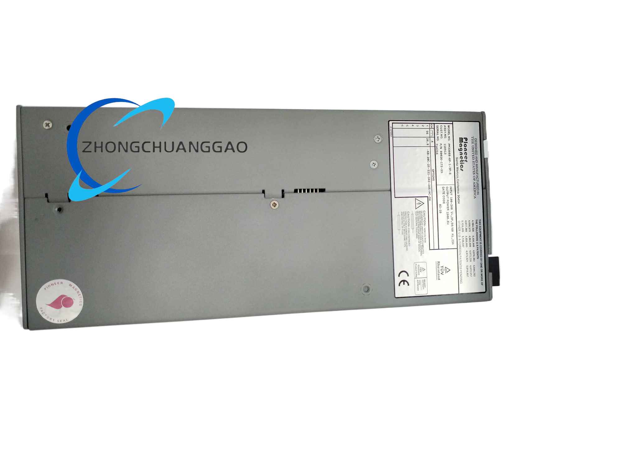
The PM3398B serves as a standardized high-power planar magnetic platform developed by Pioneer Magnetics, which can be customized with different winding configurations, current ratings, isolation voltage levels and mechanical packaging structures to form multiple dedicated variant power modules for industrial high-power energy conversion systems.
This platform adopts large-size high-power planar magnetic core design, supporting continuous high-power output operation, with optimized thermal conduction structure to realize stable full-load operation under long-term harsh industrial temperature conditions.
Description
Input Compatibility Range
Supports single-phase or three-phase universal AC input, input voltage range customizable from 90 VAC to 480 VAC
Built-in active power factor correction circuit as standard platform configuration, power factor ≥0.95 under full load
Platform supports customized rated output power from 1 kW to 3 kW per single module
Customizable continuous output current range from 5 A to 30 A according to winding parallel configuration suffix codes
Output voltage customizable from 12 VDC to 70 VDC according to customer system demand
Standard primary-secondary winding isolation withstand voltage: 2500 VAC for 1 minute without breakdown, leakage current ≤1 mA
Internal winding insulation class: F-class high-temperature resistant insulation material, long-term continuous operating temperature resistance up to 155°C
Insulation resistance between primary winding, secondary winding and module metal chassis ≥100 MΩ measured at 500 VDC test voltage
Standard unified base outline dimension: 127 mm Width × 127 mm Depth × 292 mm Height (5-inch × 5-inch standard rack-mounted packaging)
Mounting method: Standard industrial rack locking installation, supporting hot-plug Elcon drawer-type power I/O connectors as optional configuration
Housing material: Thickened aluminum alloy metal rack shell, integrated internal forced air cooling fan assembly as standard platform design
Weight of standard base platform module: Approximately 11 lbs (5 kg) without customized connector accessories
Continuous full-load operating temperature range: 0°C to +50°C, platform can deliver complete rated output power within this temperature interval
Storage temperature range with power disconnected: -40°C to +85°C
Relative humidity adaptability: 5% to 95% non-condensing operating environment
EMC performance compliance standard: IEC 61000-6-2 industrial electromagnetic immunity standard, UL and CE safety certification standard
Full set of electrical fault protection circuits integrated as standard configuration: overvoltage protection, undervoltage protection, output overcurrent protection, output short-circuit lockout protection, internal over-temperature automatic power reduction shutdown protection
Support multi-module parallel redundant hot-swap operation to realize uninterrupted power supply for critical industrial load equipment
Built-in real-time fault status monitoring circuit, external fault signal output interface reserved on front panel for upper-level SCADA monitoring system remote fault alarm collection
Internal forced air cooling fan with automatic speed regulation logic, fan rotation speed automatically increases under high load high-temperature conditions to strengthen heat dissipation, reduce fan noise under light-load low-temperature standby state
- External Rack Housing Structure
Thickened extruded aluminum alloy integrated rack shell, the metal rack serves as both mechanical protection frame and auxiliary heat dissipation channel for internal power conversion components. The front panel is equipped with detachable drawer-type power connector module, realizing hot plugging and quick module replacement without cutting off the entire rack power supply bus.
- High-Power Planar Magnetic Core Assembly
Large-size low-loss soft magnetic ferrite planar core is the universal core component of all PM3398B variant modules. Multi-layer thick copper foil parallel laminated windings are adopted for high-current output variants, effectively reducing high-frequency AC copper loss and heat generation under large current working conditions. The magnetic core assembly is fixed on the bottom aluminum alloy heat dissipation baseplate with high thermal conductivity insulating adhesive, transferring internal heat to the rack shell for forced air cooling heat exchange.
- Multi-Layer High-Current Power Circuit Board
Thick copper layer industrial FR4 printed circuit board carries all high-power switching tubes, rectifier bridge stacks, large-capacity filter electrolytic capacitors and PWM power control chips. All high-current circuit traces adopt widened thick copper layout to minimize circuit resistance and avoid abnormal heating under continuous large current load.
- Internal Forced Air Cooling Air Duct Structure
Independent sealed air duct partition design inside the aluminum rack shell, the built-in cooling fan forms directional airflow circulation through the air duct, sequentially passing the planar magnetic core assembly, power switching tube heat sinks and filter capacitor bank to take away heat generated by each high-power heating component, realizing uniform overall internal temperature distribution without local hot spot overheating phenomenon.
- AC Input Rectification & Active PFC Stage
Three-phase or single-phase alternating current input passes through front-end EMI filter network to eliminate grid high-frequency interference noise, then enters full-bridge rectifier circuit to convert AC into raw DC voltage. The built-in active power factor correction control circuit dynamically adjusts input current waveform to synchronize with input AC voltage phase, eliminating input current harmonic distortion and improving power utilization efficiency of industrial power grid.
- High-Frequency PWM Isolated Power Conversion Stage
PFC stabilized high-voltage DC bus voltage is sent to high-power full-bridge MOSFET switching tube array controlled by high-frequency PWM main control chip. The chip dynamically adjusts switching duty cycle and phase shift control logic according to real-time output voltage and current sampling feedback signals to realize closed-loop output voltage and current double closed-loop regulation. High-frequency pulsed power energy is transmitted to the secondary side through the large-size planar magnetic core assembly, which provides complete galvanic isolation between input high-voltage bus and low-voltage output load side.
- Secondary Side Synchronous Rectification & Multi-Stage Filter Stage
High-frequency alternating current induced on transformer secondary multi-parallel copper foil windings is converted to smooth low-voltage direct current through synchronous rectifier MOSFET array with low forward voltage drop, reducing rectification power loss compared with traditional diode rectifier circuits. Multi-stage LC low-pass filter network composed of high-current filter inductors and low-ESR high-capacity electrolytic capacitors eliminates high-frequency switching ripple noise on output DC voltage, providing clean stable DC power for rear-end industrial load equipment.
- Multi-Layer Fault Monitoring & Protection Execution Stage
Multiple independent real-time sampling monitoring circuits continuously collect input bus voltage, output load voltage, output load current and internal component temperature data during the entire power conversion cycle. Once any electrical or thermal operating parameter exceeds preset safe threshold values, the protection control logic immediately cuts off main PWM switching tube drive signals to lock power conversion output, avoiding permanent burnout damage to planar magnetic windings, power switching tubes and filter capacitors caused by overload, short-circuit or over-temperature faults. After fault elimination and module cooling, the protection logic automatically resets to restore normal power conversion operation.
- Parallel Redundancy & Remote Monitoring Auxiliary Logic
When multiple PM3398B variant modules are connected in parallel redundant configuration, internal current sharing control circuit automatically distributes balanced load current among all parallel modules to avoid single module overload operation. Front panel reserved fault signal output dry contact interface transmits real-time module fault status signals to upper industrial SCADA monitoring system, realizing remote real-time power supply equipment operation status monitoring and fault early warning alarm functions.
- Rack Mechanical Installation Standards
The PM3398B series modules are designed exclusively for standard industrial 5-inch rack cabinet horizontal installation; vertical or upside-down mounting is strictly prohibited, which will block internal cooling fan directional airflow circulation and lead to serious internal hot spot overheating.
Reserve minimum 30 mm vertical empty clearance space above and below the rack-mounted module to ensure unobstructed hot air exhaust and cold air intake for forced air cooling system. Do not install high heat-generating equipment such as servo drive power modules, contactor banks and high-power resistance load boxes within 15 cm horizontal distance of the module rack shell to avoid external high-temperature radiation superimposing internal heat load.
The standard Elcon drawer-type hot-plug power connector must be fully inserted and locked into the front panel connector socket after module rack installation, confirm connector locking buckle is fully engaged to prevent loose contact under equipment vibration environment causing abnormal heating and power supply interruption faults.
- Electrical Wiring Installation Specifications
Input three-phase/single-phase AC power wiring adopts high-current shielded twisted power cable with wire cross-section matched to module rated input current; all input power cable shielding layers must be reliably connected to electrical cabinet main protective earth ground bus bar to suppress power grid high-frequency electromagnetic interference.
Output load power wiring uses thick low-resistance copper cable with cross-section corresponding to module maximum output current rating; separate positive and negative output wiring layout, avoid long-distance parallel bundling of input high-voltage power cables and output low-voltage load cables to prevent cross-channel voltage coupling interference leading to output voltage fluctuation instability.
The aluminum alloy rack shell of each PM3398B module must be connected to cabinet protective earth ground bus bar with dedicated thick ground wire to eliminate static electricity accumulation on metal rack and reduce electromagnetic radiation interference to surrounding sensitive industrial control equipment.
- Environmental Installation Limitations
All PM3398B variant modules must be installed inside fully sealed dust-proof industrial electrical rack cabinets; open rack installation exposed to factory metal cutting dust, machine tool oil mist, corrosive acid/alkali chemical gas and direct water splash is forbidden, these contaminants will corrode internal circuit board traces, planar magnetic winding insulation layers and cooling fan bearing components, leading to permanent module hardware failure.
Avoid installing the module rack near equipment cooling fan exhaust outlets; high-speed exhaust airflow carrying dust particles will continuously accumulate on module front panel connectors and internal cooling air duct filter screens, blocking cooling airflow and gradually reducing heat dissipation efficiency during long-term continuous operation.
Reviews
There are no reviews yet.