
Product Short Description
Product Overview
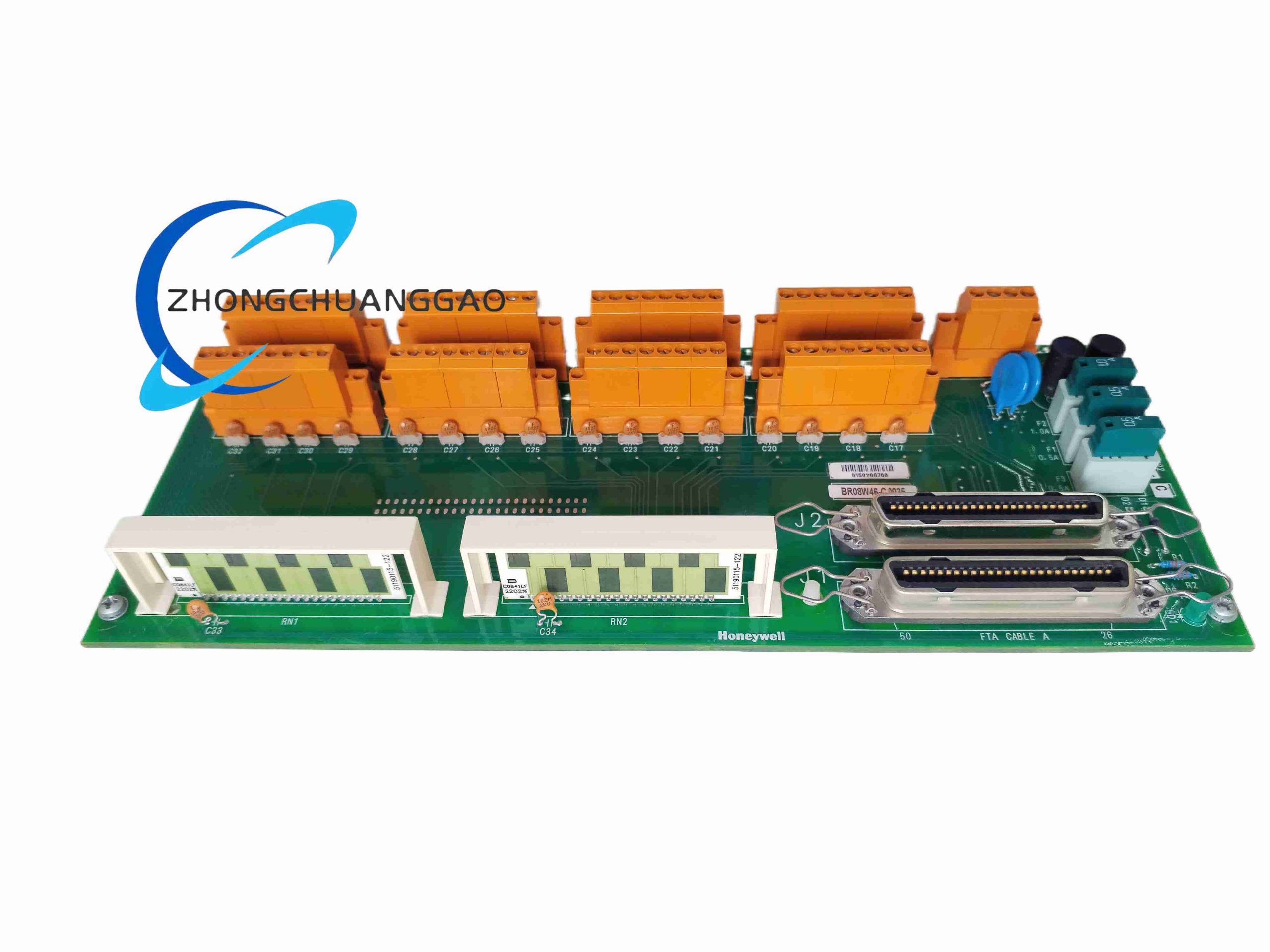
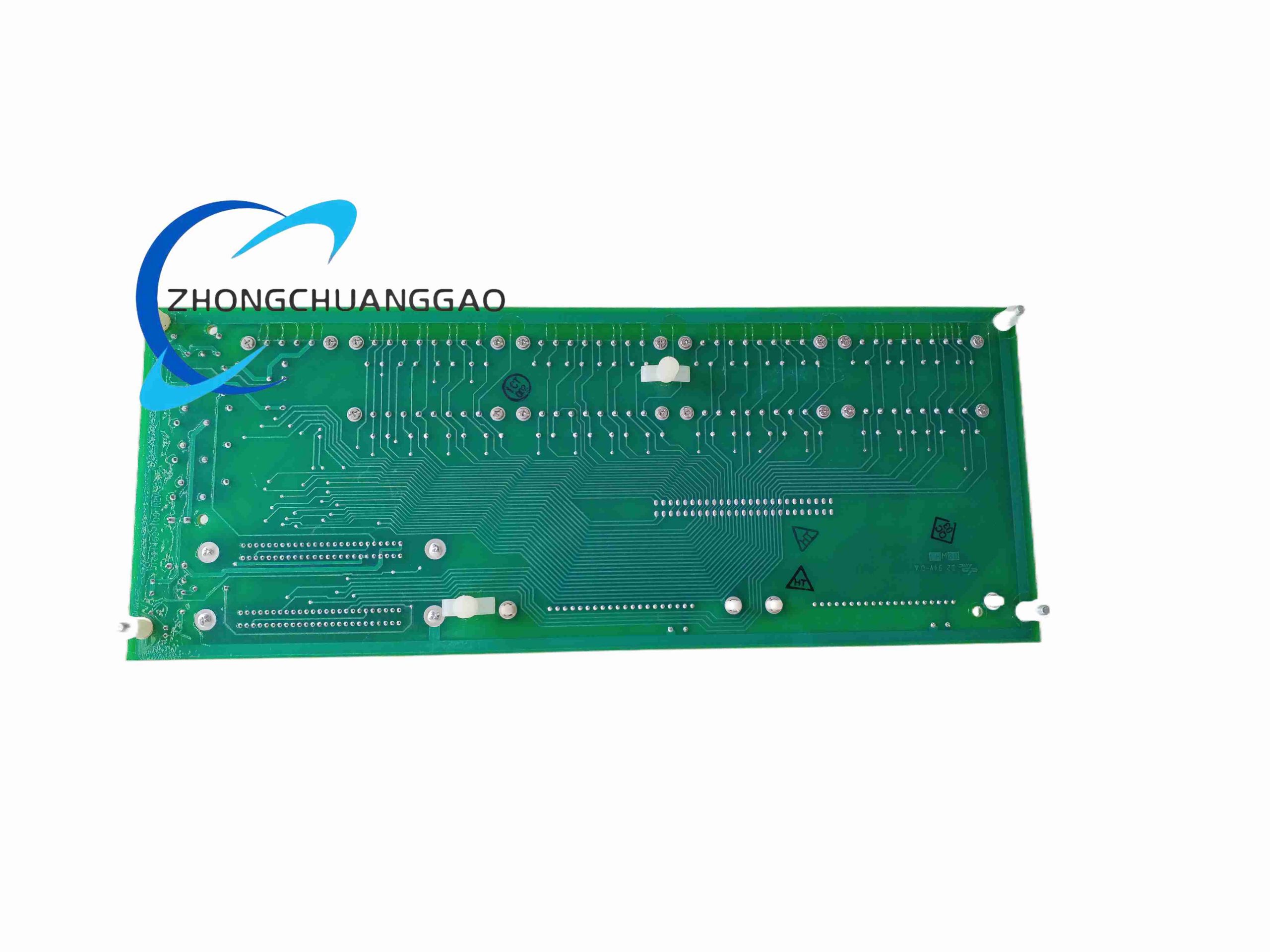
MC-TDIY22 (part code 51204160-175) is the field wiring terminal board matched with MC-PDIY22 digital input processor card. It receives 24VDC contact switch signals from field limit switches, pressure transmitters and interlock sensors, performs signal filtering and opto-isolation, then transmits standardized digital signals to DCS main processor card via shielded ribbon cable.
Description
Core Technical Specifications
- Total Input Channels: 32 isolated digital input points
- Nominal Input Voltage: 15–30 VDC (standard 24 VDC field switch signal)
- Single Channel Input Current: 2 mA at 24 VDC input
- Input Impedance: >10 MΩ, low power consumption
- Isolation Strength: 1500 VAC optocoupler galvanic isolation per channel
- Supported Signal Types: Contact closure, NPN open collector, TTL level switch signals
- Terminal Type: Quick-disconnect compression spring terminals, no screwdriver required
- Operating Temperature: -40°C ~ +70°C
- Storage Temperature: -40°C ~ +85°C
- Vibration Resistance: 5–25 Hz, 0.8 mm peak-to-peak amplitude
- Shock Resistance: 15 g, 11 ms half-sine impact pulse
- Physical Weight: 0.77 kg
- PCB Protection: Full surface polyurethane conformal coating
Function Features
- 32 independent input channels, each with independent overvoltage and reverse polarity protection
- Built-in RC low-pass filter circuit to eliminate field contact bounce and high-frequency EMI interference
- Channel status indicator LED for on-site quick fault diagnosis of open/short circuit
- Two 50-pin gold-plated ribbon cable connectors for connection to MC-PDIY22 processor module
- Modular marshalling cabinet layout design, supports system redundancy configuration
- Compression spring terminals allow fast field wiring modification without special tools
- Anti-reverse insertion connector design to prevent wrong cable connection damage
Working Principle
Field sensor switch signal (24VDC high/low level) accesses corresponding channel spring terminal, passes RC filter circuit to eliminate contact bounce noise. The filtered signal drives optocoupler input side, converting field-side electrical signal into optical signal to achieve complete isolation between field and control cabinet circuit. Optocoupler output side converts optical signal back to digital logic level, transmitted through ribbon cable to DCS MC-PDIY22 processor card for signal collection and logic judgment. Each channel LED lights up when input signal is active for visual status feedback.
Material & Structural Characteristics
- Circuit Board: Thick FR4 green solder mask PCB, full conformal coating for anti-corrosion
- Terminal Components: Orange PA66 flame-retardant spring compression terminals
- Connector: Gold-plated multi-pin ribbon cable sockets with locking buckles
- Fixing Hardware: Stainless steel mounting studs for panel rack installation
- Silicone shock-absorbing pads between PCB and mounting plate to resist cabinet vibration
Installation Requirements
- Mount vertically inside DCS marshalling cabinet with four fixing studs
- Separate field signal wiring from high-current power cables with partition board to avoid interference
- All field switch cables adopt twisted shielded wire, single-point grounding at cabinet earth bar
- Ribbon cable between MC-TDIY22 and MC-PDIY22 must be original Honeywell shielded cable
- Keep ambient humidity below 95% non-condensing, avoid cabinet internal water vapor condensation
- Maintain 10 mm minimum gap between adjacent FTA boards for air circulation
Application Scenarios
- Process plant on-site valve limit switch, pump running feedback signal collection
- Safety interlock door, emergency stop button, fire alarm digital signal input
- Power plant auxiliary equipment temperature switch, pressure alarm contact signal
- Water treatment tank liquid level switch, flow switch status acquisition
- Chemical factory safety barrier contact input signal collection
- Building energy management system air valve, fan operation feedback monitoring
Operation & Maintenance Notes
- Disconnect all field 24VDC power supply before modifying terminal wiring
- Check LED indicator status during routine inspection to quickly locate disconnected field sensors
- Do not apply voltage exceeding 30 VDC to any input channel to avoid optocoupler burnout
- Clean PCB surface with dry compressed air only, liquid cleaning is prohibited
- Replace aging ribbon cables every 5 years to prevent signal interruption caused by pin oxidation
- For redundant DCS systems, ensure two sets of FTA boards share independent field power supply loops
-500x500.jpg)
Reviews
There are no reviews yet.