
Product Short Description
Product Brief Introduction
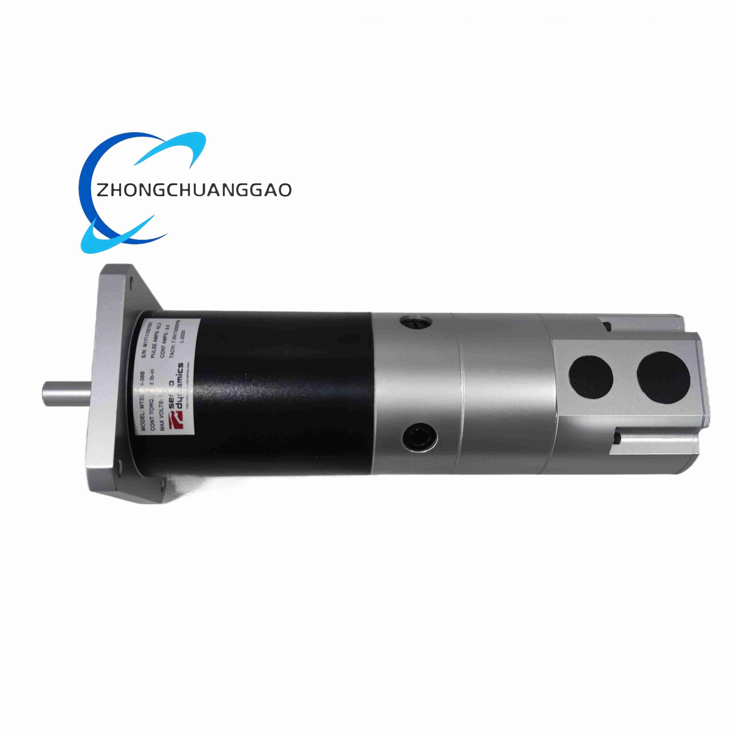
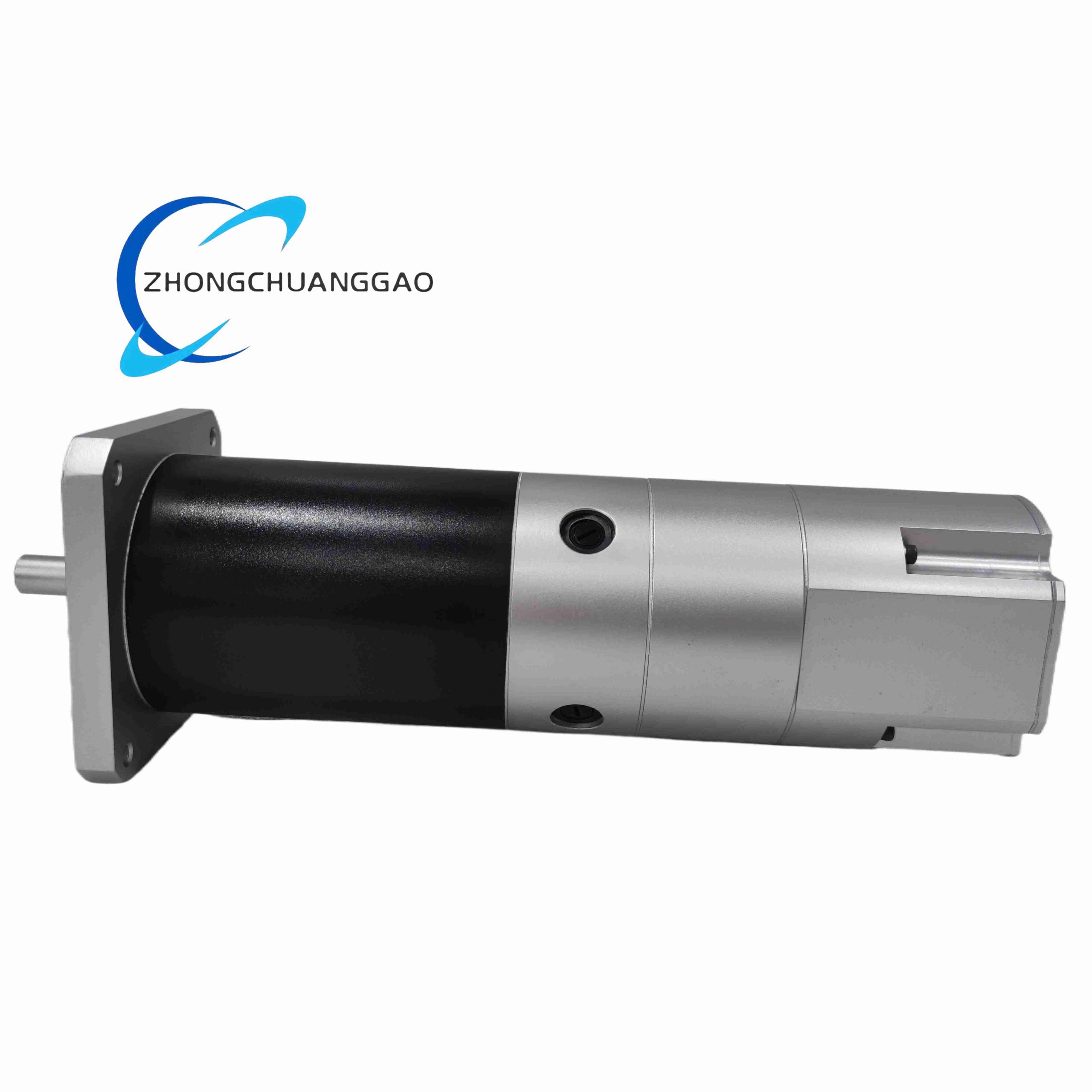
MTS30M4-38C is an integrated gearbox DC servo motor manufactured by SEM Motion Control, combining high-performance permanent magnet brushed servo motor and precision planetary gear reducer into a single compact unit. Optimized for compact automation equipment requiring high continuous torque output under limited installation space, widely integrated into robotic joints, automated positioning stages and precision industrial actuators.
Description
Core Technical & Performance Parameters
- Motor Type: PM Brushed DC Servo Motor with Integrated Planetary Gear Reducer
- Rated Continuous Torque Output: 2.9 N·m
- Peak Overload Torque Capacity: 8.7 N·m short-duration shock load
- Rated Operating Voltage: 24 VDC industrial control power supply
- Rated Continuous Current: 3 A DC; Peak Overload Current 9 A DC
- Maximum No-Load Rotational Speed: 6000 RPM motor shaft, reduced output speed matched gear ratio
- Integrated Gearbox: Precision 4-stage planetary gear reducer, low backlash design
- Encoder Interface: Rear mounting flange compatible with incremental rotary position encoders
- Net Unit Weight: 1.5 kg complete motor + gearbox assembly
- Operating Ambient Temperature: -20°C ~ +85°C
- Storage Temperature Range: -40°C ~ +100°C
- Enclosure Protection Grade: IP54 standard factory coating
- Certification: CE, RoHS industrial compliance
Functional Features
- Integrated motor-planetary gear reducer monoblock design eliminates separate gearbox coupling installation
- Ultra-low gear backlash for high-precision angular positioning accuracy
- High peak torque overload capacity for rapid acceleration and dynamic load response
- High-energy neodymium permanent magnet rotor minimizes cogging torque for smooth low-speed rotation
- Class F high-temperature winding insulation sustains long continuous duty cycle operation
- Double sealed ball bearing layout for gearbox output shaft under radial and axial mechanical loads
- Modular rear encoder mounting flange compatible with standard industrial rotary feedback sensors
- Low electromagnetic interference winding construction to avoid analog sensor signal distortion
Working Principle
DC control current supplied to stator windings generates electromagnetic torque acting on permanent magnet rotor, driving high-speed motor shaft rotation. Integrated multi-stage planetary gear reducer converts high-speed low-torque motor rotation to low-speed high-torque output shaft motion with precise speed reduction ratio. External encoder mounted to rear motor flange provides real-time position and velocity feedback to servo drive, enabling closed-loop PID torque, velocity and position regulation. Planetary gear train distributes mechanical load evenly across multiple gear teeth to extend service life and reduce transmission backlash error.
Material Composition
- Main Motor Housing: Die-cast aluminum alloy black hard anodized anti-corrosion coating
- Gearbox Housing: High-strength cast aluminum alloy with precision machined flange mounting surface
- Rotor Permanent Magnets: High-energy neodymium rare-earth magnets
- Motor Output Shaft & Gear Components: Quenched alloy steel precision ground gear teeth
- Stator Lamination: Low-loss silicon electrical steel sheet to reduce winding heat generation
- Brush Assembly: Copper-graphite composite wear-resistant brush contacts
- Bearings: Chromium alloy steel sealed ball bearings with high-temperature synthetic grease
- Terminal Connector: Aviation-grade metal shielded wiring plug with flame retardant PA66 plastic insulation
Structural Characteristics
- Coaxial integrated motor + planetary gear reducer compact cylindrical monoblock structure
- Front square mounting flange with standardized bolt hole pattern for direct machine frame bolt-on installation
- Single solid precision ground output shaft with keyway for load coupling connection
- Separated rear end cap aviation plug power connector and encoder feedback mounting flange
- External heat sink fin structure on motor housing surface for passive natural convection cooling
- Sealed brush access panel for periodic brush wear replacement without gearbox disassembly
- Multi-stage planetary gear internal load balancing design to reduce gear tooth wear and vibration
Installation Requirements
- Mount via front flange using Grade 8 alloy steel bolts, evenly torque fasteners to prevent housing distortion
- Maintain minimum 15mm air clearance around motor/gearbox housing for passive heat dissipation
- Install flexible bellows coupler to output shaft to eliminate side radial load and axial thrust force
- Separate shielded motor power cable and encoder feedback cable with minimum 15cm wiring gap to reduce EMI interference
- Ground cable shielding single-ended at servo drive cabinet only; avoid multiple grounding loops
- Horizontal mounting recommended; vertical mounting allowed only with factory-specified top-side heat sink orientation
- Installation location must avoid continuous liquid splash, oil mist accumulation and UV radiation exposure
Application Scenarios
- Small collaborative robotic arm joint drive actuators
- Semiconductor automated wafer handling precision rotary positioning stages
- Medical laboratory automated test equipment rotary drive axes
- Packaging machinery small indexing rotary tables
- CNC micro-machine tool low-speed high-torque feed axes
- Automated valve compact electric rotary actuators
Operation & Maintenance Precautions
- Do not sustain peak overload torque for longer than 3 consecutive seconds to prevent magnet demagnetization and gear tooth fatigue
- Inspect brush wear every 1000 operating hours; replace brush assemblies when residual length < 3mm
- Never operate unit without encoder feedback signal; open-loop operation causes uncontrolled over-speed damage
- Avoid continuous operation at ambient temperature above 70°C without auxiliary forced air cooling
- Prevent direct impact force on output shaft and keyway during transportation and installation to avoid shaft bending and gear internal misalignment.
- Do not operate the motor under locked rotor condition for extended durations; locked rotor leads to rapid winding temperature rise and permanent insulation failure.
- For long-term idle storage, place the unit in dry, constant-humidity environment and support the output shaft horizontally to avoid bearing indentation caused by static load.
- Avoid frequent rapid forward-reverse switching without proper acceleration ramping; frequent reversal will accelerate gear surface fatigue and increase backlash.
Reviews
There are no reviews yet.