
Product Short Description
Product Brief Introduction
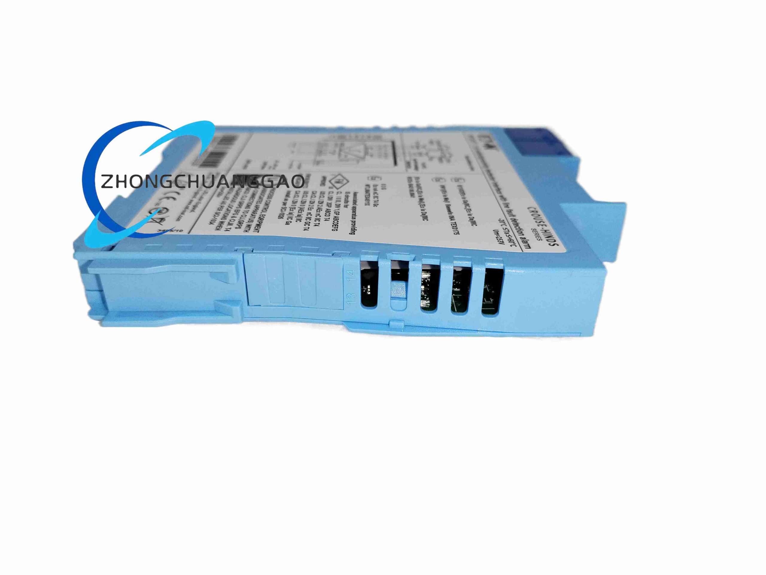
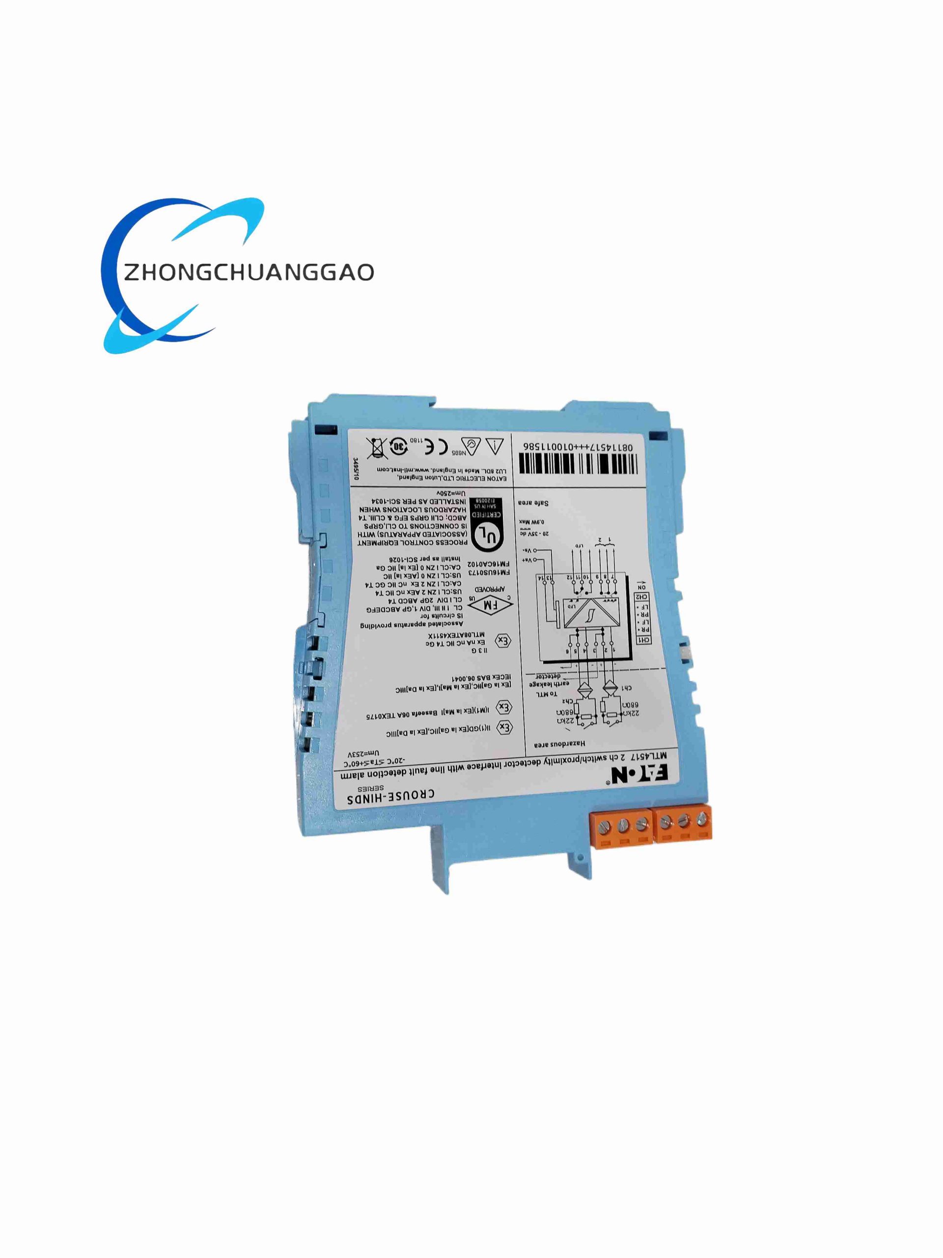
MTL4517 belongs to Eaton MTL4500 series 28V intrinsically safe relay barriers, used to isolate digital contact switch signals between hazardous explosive areas and safe control cabinets. Equipped with built-in Line Fault Detection circuit to diagnose open or short-circuit field wiring, supporting SIL 2 safety loop applications for process safety systems
Description
Core Technical & Performance Parameters
- Intrinsic Safety Rating: Ex ia IIC T6, Zone 0 / Zone 1 certified
- Relay Contact Type: Single-pole double-throw (SPDT / changeover)
- Maximum Safe Voltage (Ui): 28 VDC
- Maximum Safe Current (Ii): 93 mA
- Contact Power Rating: Max 10W, 0.5A, 250V AC resistive load
- Relay Response Time: ≤10 ms actuation delay
- LFD Alarm Threshold: Open circuit trigger >250μA leakage; short circuit trigger <100Ω loop resistance
- Operating Temperature Range: -20°C ~ +60°C
- Mounting: 35mm DIN rail
- Safety Integrity Level: SIL 2 capable per IEC 61508
- Isolation Voltage: 2500 VAC galvanic isolation between hazardous and safe sides
Functional Features
- SPDT changeover relay contacts provide normally open and normally closed dry contact outputs for control logic
- Integrated LFD line fault detection continuously monitors field switch wiring integrity
- Full galvanic isolation eliminates ground loop interference between hazardous and safe zone circuits
- SIL 2 certification suitable for safety instrumented system (SIS) digital input loops
- Slim single-channel DIN rail module, high cabinet packing density
- LED status indicators for relay actuation state and wiring fault alert
- Reverse polarity protection on hazardous area field wiring terminals
Working Principle
Hazardous area dry contact switch signal passes through intrinsic safety current/voltage limiting barrier circuits to drive internal low-power isolation relay coil. Relay mechanical contacts transfer switch state to safe-area control circuit. Onboard LFD circuit injects tiny monitoring current into field wiring to continuously measure loop resistance; resistance outside calibrated threshold triggers fault alarm signal transmitted to DCS/PLC. Zener barrier components restrict maximum energy entering hazardous area to meet Ex ia safety standards.
Material Composition
- Module Housing: Flame retardant V0 black ABS plastic
- Relay Core: Epoxy-sealed miniature electromagnetic isolation relay
- Safety Barrier Circuit: Precision Zener diodes, wire-wound power resistors, ceramic gas discharge tubes
- Terminals: Nickel-plated copper screw terminals, PA66 flame retardant plastic
- Mounting Spring Clips: Zinc-plated spring steel
Structural Characteristics
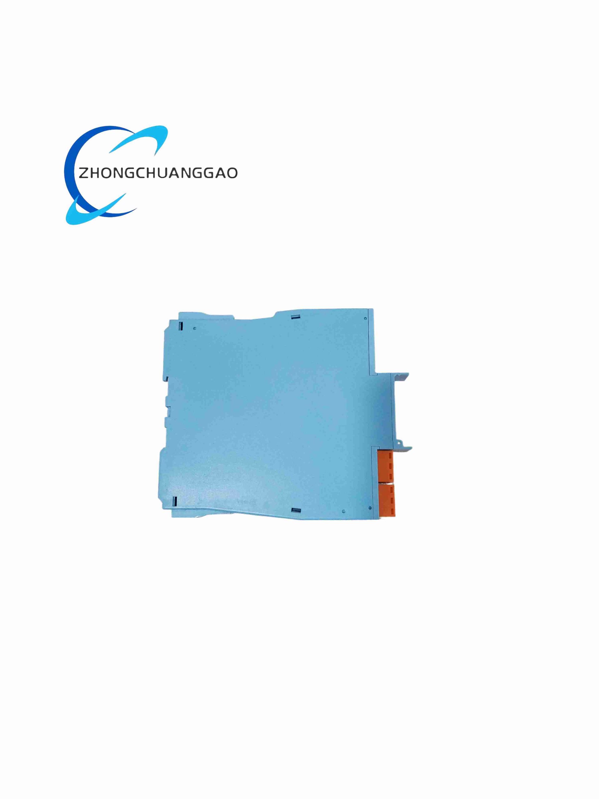
- Single-width slim DIN rail module form factor
- Separate terminal blocks: left hazardous field side terminals, right safe cabinet side terminals
- Front-facing bi-color LED indicators for power, relay status and wiring fault
- Snap-on terminal protective cover to prevent accidental short-circuit during wiring maintenance
Installation Requirements
- Mount inside safe-area control cabinet only; field wiring extends into hazardous Zone 0/1
- Maintain 3mm minimum gap between adjacent MTL series barrier modules for heat dissipation
- Hazardous field wiring must use intrinsically safe shielded cables, sealed via certified cable glands
- LFD function requires series 500Ω~1kΩ resistor with field contact switch per datasheet instruction
- All wiring torque screws to specified 0.8 N·m torque to avoid loose contact resistance drift
- Safe-side contact wiring must add freewheeling diode for inductive loads (solenoids, contactors)
- Ground module DIN rail bus bar to cabinet protective earth single point
Application Scenarios
- Oil & gas hazardous zone limit switch and valve position feedback signal isolation
- Chemical plant SIS safety interlock dry contact input signal barrier
- Refinery explosion-proof door, emergency stop digital signal transmission
- Offshore platform fire & gas detector contact output isolation
- Pharmaceutical classified explosion zone equipment interlock monitoring
Operation & Maintenance Precautions
- Do not exceed 10W contact power rating to avoid relay contact pitting and premature failure
- Verify LFD resistor installation after every field switch wiring modification
- Replace module if fault LED remains latched after confirmed field wiring repair
- Inductive loads on safe-side relay contacts must install surge suppression components
- Do not connect voltages exceeding 28V DC to hazardous side field terminals
- Annual functional test of relay switching and LFD fault detection circuit required for SIL 2 safety loops
- Avoid installation in cabinet areas with continuous temperature above 60°C
Reviews
There are no reviews yet.