
Product Short Description
Product Brief Introduction
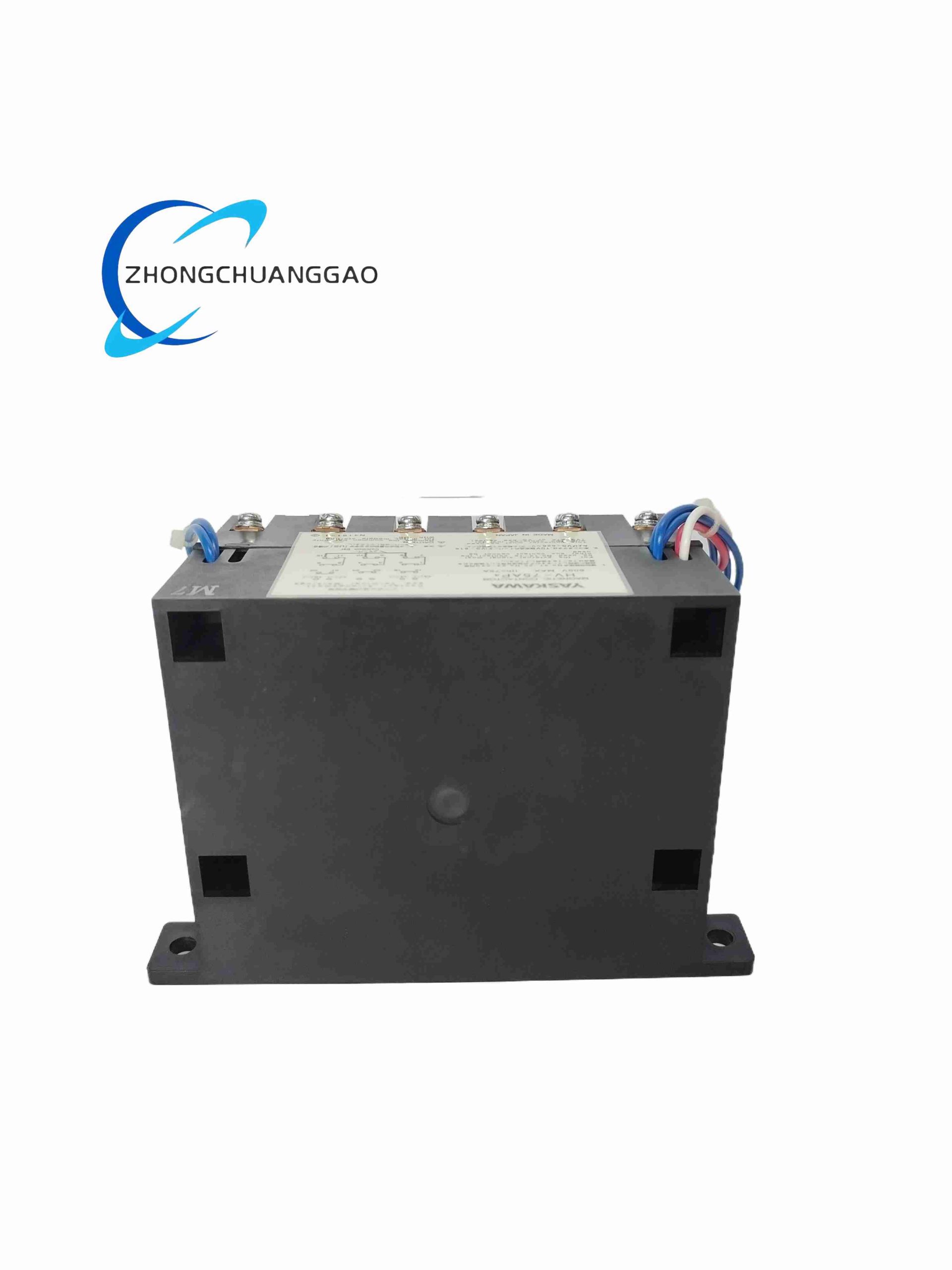
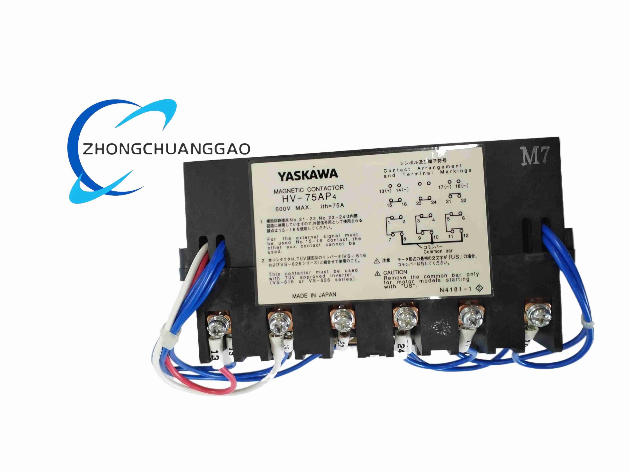
YASKAWA HV-75AP4 is dedicated heavy-duty AC magnetic contactor designed for matching Yaskawa VS-616/626 series industrial frequency inverters, rated 75A main circuit current for medium-heavy load motor drive systems. It provides reliable main circuit switching, short-circuit isolation protection for inverter input power loop, built-in arc suppression circuit to extend inverter IGBT power module service life, certified TUV safety standard for industrial variable frequency drive applications.
Description
Core Technical Specifications
- Main Circuit Rated Parameter:
- Rated operational current: 75A three-phase AC
- Rated insulation voltage: 600V AC industrial power grid
- Applicable input voltage: Three-phase 200V AC 50/60Hz inverter main circuit
- Control Coil Specification: Standard AC control coil compatible with industrial control cabinet 110V/220V AC control power supply
- Contact Structure: Three main power poles + 1 auxiliary normally open + 1 auxiliary normally closed signal contact
- Arc Suppression: Integrated RC absorption arc suppression circuit on main contact terminals to eliminate switching voltage surge
- Mechanical Lifespan: ≥10 million mechanical operations without load
- Electrical Lifespan: ≥1 million electrical make-break cycles under rated 75A load
- Mechanical Dimension: Compact DIN rail mount frame size, weight approx. 2kg
- Protection Class: IP20 internal cabinet installation rating
- Ambient Operating Condition: -10°C ~ +50°C, humidity 5–90% non-condensing
Function & Performance Features
- Special optimized contact alloy material matched for inverter front-end power switching, resistant to DC arc erosion generated by rectifier circuit switching
- Built-in RC arc suppression absorption circuit suppresses high voltage surge during contact breaking to protect inverter internal rectifier bridge and IGBT power semiconductors
- Auxiliary NO/NC signal contacts feedback contactor closed/open state to PLC for interlock logic control
- High mechanical shock resistant structure tolerates vibration from fan, pump, conveyor motor workshop operation
- Low coil power consumption design reduces control cabinet heat accumulation with multiple contactor layout
- Standard screw-type wiring terminals allow large cross-section power cable connection for 75A rated current
- TUV safety certification compliant with European industrial drive equipment safety standards
- Compact body design saves electrical cabinet layout space for multi-drive system integrated control panels
Working Principle
When PLC control logic sends closing signal to contactor electromagnetic coil, magnetic field pulls movable iron core to drive three-phase main power contacts closed, conducting three-phase AC mains power to frequency inverter input terminal. Auxiliary contact linkage synchronously switches NO/NC signal state for PLC feedback monitoring. When coil power cuts off, spring mechanical force separates main contacts to disconnect inverter main circuit power supply. Integrated RC absorption circuit absorbs inductive switching arc energy generated during contact separation to avoid high surge voltage damaging inverter internal power components.
Material & Structural Characteristics
- Main Power Contacts: Silver-tin cadmium alloy composite contact material, high arc ablation resistance for frequent inverter switching cycles
- Electromagnetic Coil Winding: High-temperature resistant enameled copper wire, thermal insulation class F
- Housing Shell: Black UL94-V0 flame retardant thermoplastic engineering plastic
- Arc Chamber: Plastic arc extinguishing grid structure, rapidly cool and extinguish electric arc during contact breaking
- Terminal Blocks: Thick copper conductive terminals with nickel plating anti-oxidation, large wire clamping range for high-current power cables
Installation Requirements
- Standard 35mm DIN rail snap-on mounting inside inverter control cabinet
- Install dedicated 90A rated fast-blow fuse upstream of contactor three-phase input power terminal for short-circuit overcurrent protection
- Separate high-current main power wiring and low-voltage control coil wiring with ≥4cm clearance to reduce EMI interference
- Vertical mounting orientation only; horizontal installation reduces arc chamber extinguishing performance and shortens electrical lifespan
- Reserve ≥10mm vertical gap between adjacent contactors for heat dissipation under continuous heavy load operation
- Auxiliary signal contact wiring use shielded twisted pair cable for PLC feedback signal anti-interference
Typical Application Scenarios
- Yaskawa VS series frequency inverter front-end main circuit power isolation switching
- Medium-power conveyor belt, fan, water pump variable frequency drive system power control
- Metal processing machine tool main spindle inverter input circuit safety isolation
- Packaging machinery, textile printing equipment multi-inverter cabinet power distribution switching
- HVAC central air conditioning large fan inverter power cut-off interlock protection
Operation & Maintenance Precautions
- Verify coil control voltage specification matches cabinet control power before wiring to avoid coil burnout
- Quarterly inspection of main contact surface ablation; replace contactor if contact pitting or gap increase visible
- Do not install contactor within 30cm distance of inverter heat exhaust vent; high temperature accelerates contact alloy aging
- Disconnect upstream main circuit fuse power supply before contactor disassembly and wiring maintenance
- Avoid frequent make-break operation over 10 cycles per minute to reduce electrical contact wear rate
- Regular coil insulation resistance test every 6 months in high-humidity factory cabinet environments
- Do not remove built-in RC arc suppression circuit; removal voids inverter surge voltage protection performance
Reviews
There are no reviews yet.