
Product Short Description
Product Overview
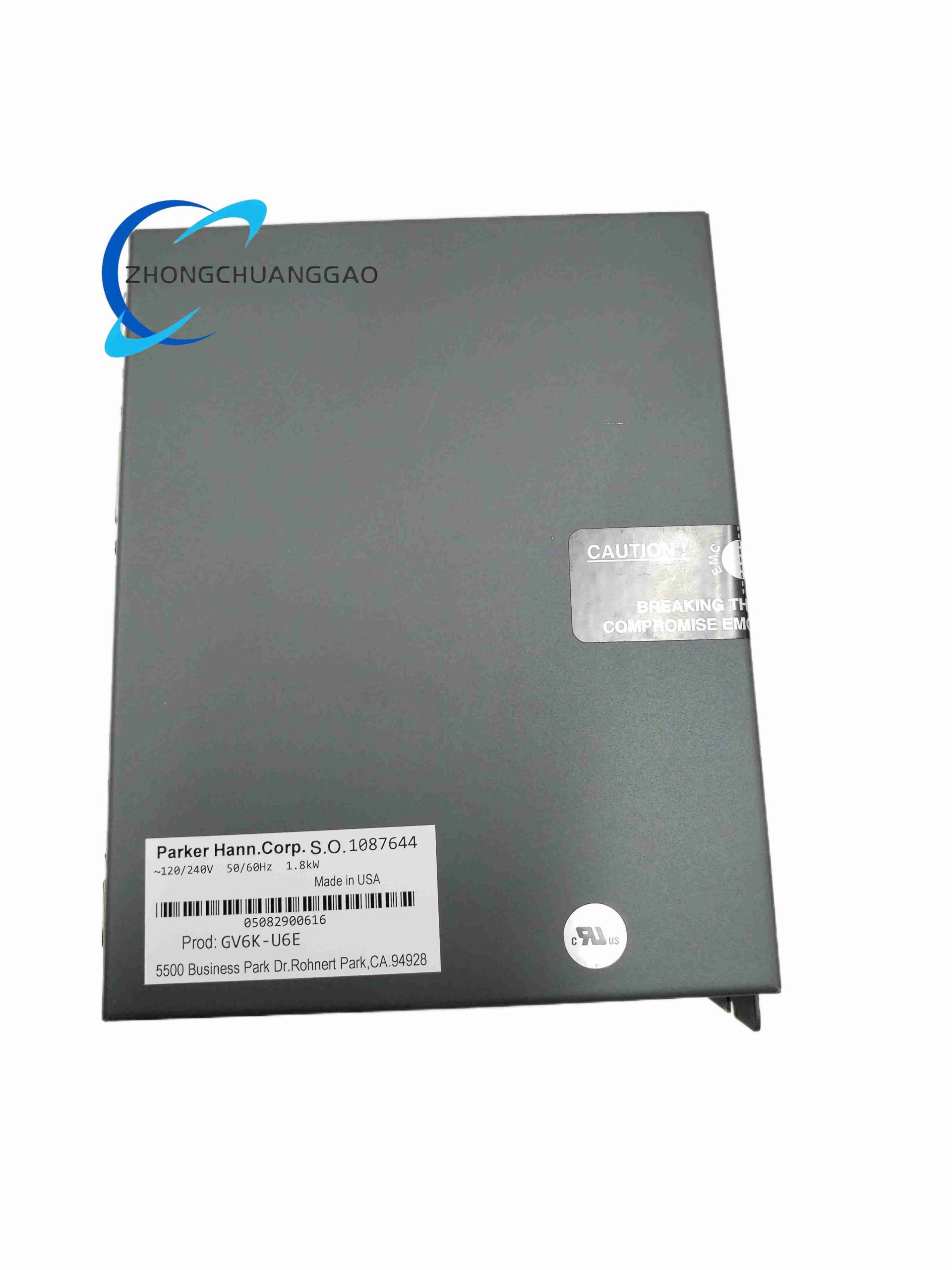
GV6K-U6E is an integrated single-axis servo drive + standalone motion controller from Parker Gemini GV6K series, combining motion programming logic and power drive stage into a single compact unit, eliminating separate PLC and servo amplifier hardware for single-axis positioning equipment. The U6E designation represents universal 95–265VAC single-phase input, 6A continuous output current
Description
Core Technical Specifications
- AC Input Power: Single-phase universal 95–265VAC 50/60Hz auto-adaptive
- Drive Output Rating: 6A RMS continuous current; 15A peak short-duration current; 1.75kW maximum continuous motor power
- DC Bus Voltage: 170/340VDC auto-switchable based on input AC voltage
- PWM Switching Frequency: Configurable 8kHz / 16kHz / 20kHz
- Motion Control Performance: Servo update cycle 62.5μs per axis; position range ±2,147,836,480 encoder counts
- Command Interfaces: ±10V analog velocity/position command, step & direction pulse input, ASCII serial command communication
- Feedback Support: Differential TTL incremental encoder (max 12MHz quadrature frequency); home and limit switch digital inputs
- Environmental Parameters: Still air max operating temp 45°C; forced airflow up to 50°C; humidity 0–95% non-condensing
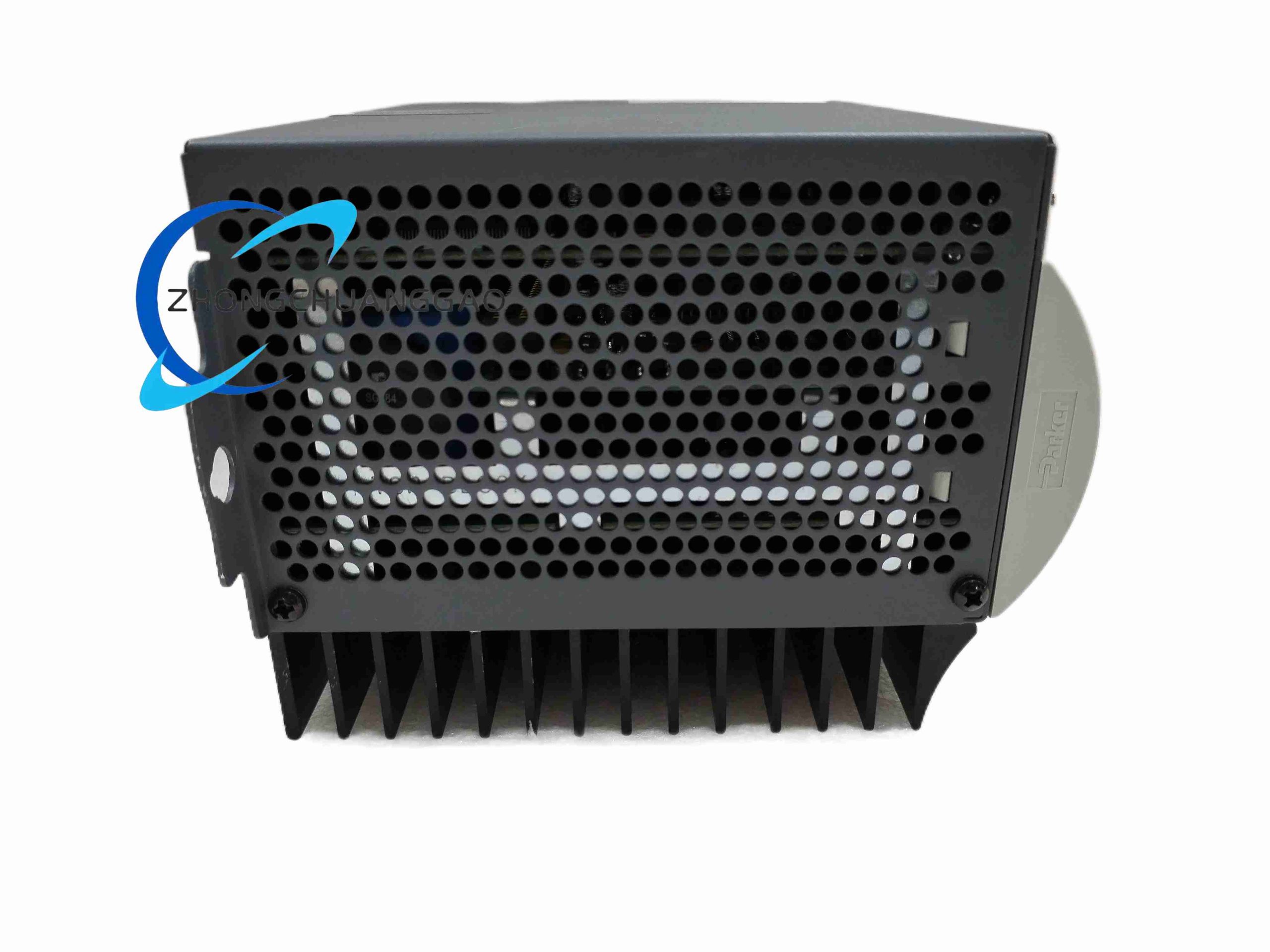
- Physical Dimension: 132mm(W) × 245mm(H) × 108mm(D); weight 1.6kg; panel rear mounting via screw lugs
Function Features
- All-in-one integrated design: onboard motion programming interpreter eliminates external motion controller hardware cost
- Built-in electronic cam, electronic gearing, position following (master-slave tracking) and segmented motion profile functions
- 17 configurable fast trigger digital inputs for home, travel limit, sensor capture, and machine interlock signals
- Full ASCII serial command protocol compatible with third-party HMI, PLC, and industrial SCADA systems via RS232/RS485
- Automatic servo loop gain tuning wizard to optimize position/velocity loop bandwidth for different mechanical load stiffness
- Comprehensive fault protection: overcurrent, overvoltage, undervoltage, over-temperature, encoder loss, travel limit overrun
- Non-volatile program memory stores complete motion sequencing logic without continuous power retention
Working Principle
- Single-phase universal AC input rectified to DC bus voltage via internal power supply stage
- Onboard motion CPU executes user-written G-code-style motion programs stored in Flash memory, generating target position trajectory profiles
- Target position command compares with real-time differential encoder feedback signal to calculate position error value
- PID servo control loop processes position error to output velocity command to internal PWM power drive stage
- IGBT inverter converts DC bus voltage to three-phase variable frequency AC to drive permanent magnet servo motor
- RS232/RS485 serial bus exchanges motion program upload/download, real-time position data, and fault codes with upper control equipment
Material & Structural Characteristics
- Outer Chassis: Cold-rolled steel sheet housing with matte black anti-rust powder coating
- Heat Dissipation System: Vertical aluminum alloy fin heat sink integrated on unit rear panel for passive cooling
- Control Circuit Board: Multi-layer PCB with isolated analog feedback and digital communication zones to suppress EMI noise
- Terminal Connectors: Screw terminal power block, D-Sub encoder feedback port, DB9 serial communication port
- Mounting Hardware: Two integrated metal lugs on top rear for direct cabinet panel screw fastening
Installation Requirements
- Mount vertically on cabinet rear panel with heat sink fins exposed to unobstructed cooling airflow; reserve 80mm clearance top and bottom
- Single-phase AC input wiring uses 1.5mm² copper cable with 16A circuit breaker upstream power protection
- Servo motor power cables and encoder feedback cables must run in separate cable ducts with minimum 10cm separation
- All shielded cable shielding layers terminate to cabinet grounding bar at single end only
- Install external 24VDC power supply for limit/home switch digital input circuits as required by machine wiring schematic
Usage Precautions
- Do not run drive continuously above 70% rated 6A continuous current without cabinet forced cooling fans
- Save motion program backup file to PC storage before firmware upgrade or unit replacement
- Adjust PWM switching frequency to 8kHz for high-inductance large-frame motors to reduce switching heating loss
- Do not connect/disconnect encoder D-Sub cables under live power to avoid feedback chip damage
- Execute limit switch homing procedure after mechanical disassembly to re-establish machine absolute zero position reference
Reviews
There are no reviews yet.