
Product Short Description
Product Overview
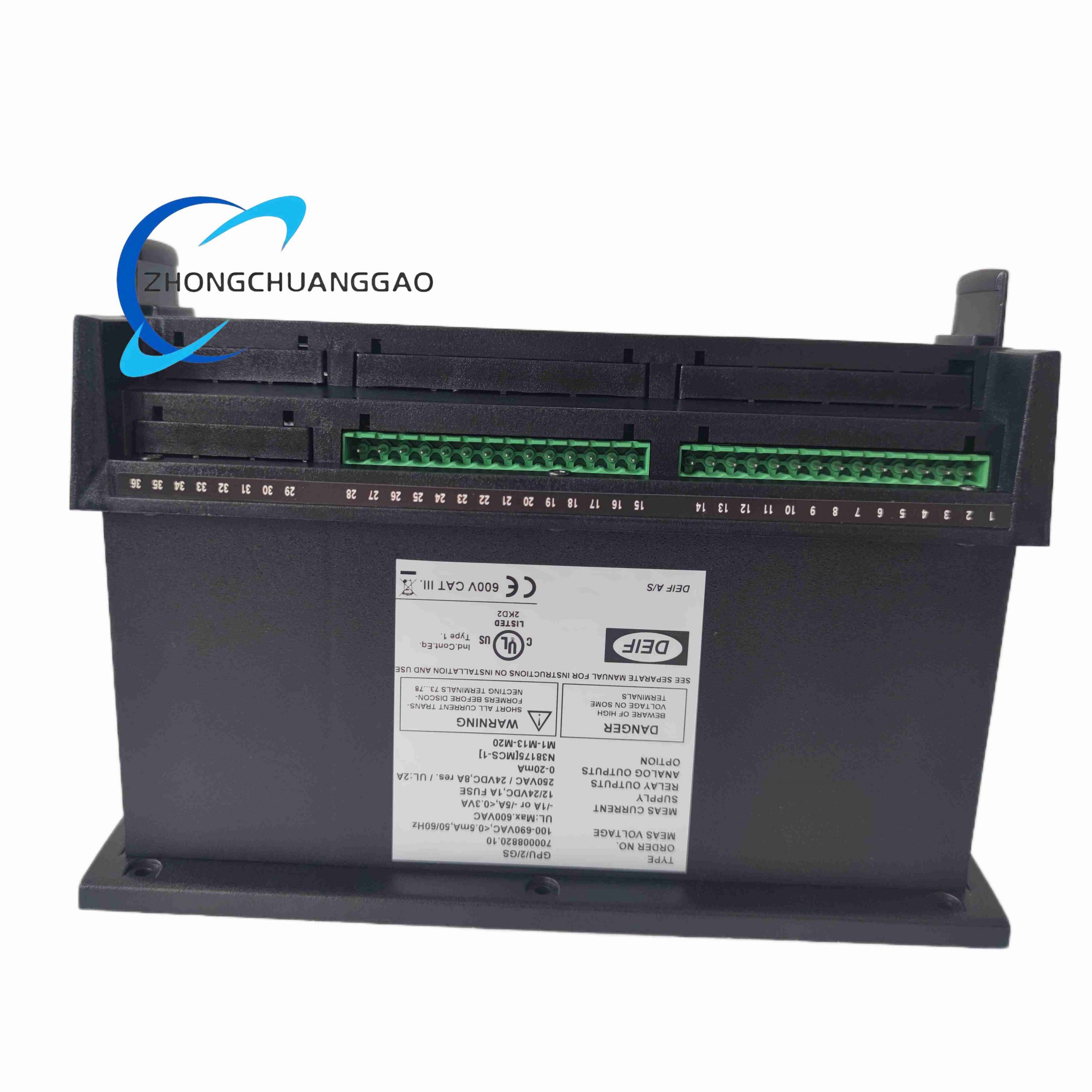
GPU2GS is a second-generation universal generator protection unit from Danish brand DEIF, dedicated to single and parallel diesel/gas genset power system monitoring and fault protection. It continuously measures three-phase generator electrical parameters and executes programmable fault trip interlocks to safeguard alternators from voltage, frequency, phase sequence, and overload damage.
Description
Core Technical Specifications
- Measuring Range: 3-phase line voltage 100–690VAC; frequency 30–70Hz; phase sequence detection
- Auxiliary Power Supply: 24VDC isolated auxiliary power, tolerance ±20%; consumption max 5W
- Relay Outputs: Four programmable SPDT relay outputs (alarm or trip mode configurable)
- Communication Interface: Modbus RTU, CANopen DEIF proprietary bus for genset system networking
- Display & Operation: Backlit 4-line LCD screen + membrane keypad for on-site parameter programming
- Environmental Rating: Operating -40°C ~ +70°C; humidity 5–95% non-condensing; IP20 front panel
- Mounting Standard: 35mm DIN rail mounting; cutout panel mounting compatible
- Physical Dimension: 120mm(W) × 85mm(H) × 60mm(D); unit weight 350g
Function Features
- Full three-phase continuous monitoring: overvoltage, undervoltage, overfrequency, underfrequency, reverse phase sequence, unbalanced voltage trip
- User-programmable fault delay timers to avoid false tripping from transient grid fluctuations
- Real-time display of voltage RMS value, frequency, fault event code, and relay status on LCD
- Stored fault history log records last 50 fault trigger events with timestamp for maintenance troubleshooting
- Compatibility with all DEIF genset controllers (AGC series, PPC series) and third-party power PLC systems
- Isolated analog input channel accepts external 4–20mA signals for reverse power, current, or temperature monitoring
- Built-in surge protection on voltage measurement terminals to withstand generator switch transient spikes
Working Principle
- Voltage transformers step down generator high three-phase voltage to low-level measurement signals for internal analog sampling circuit
- Onboard DSP chip calculates RMS voltage, frequency, and phase rotation sequence at 10ms sampling cycle
- Compares measured electrical parameters against user-configured protection threshold values stored in non-volatile Flash memory
- When parameter exceeds threshold for longer than programmed delay time, drive corresponding relay output to trigger generator circuit breaker trip or local audible alarm
- Transmit all real-time electrical data and fault codes via Modbus/CAN bus to remote power monitoring SCADA system
- Membrane keypad enables field technicians to modify protection thresholds, reset fault logs, and perform unit self-test without PC software
Material & Structural Characteristics
- Outer Housing: Flame-retardant gray PC plastic DIN rail enclosure with integrated snap mounting clip
- Display Module: Transflective LCD with LED backlight for clear visibility under direct sunlight
- Terminal Blocks: Spring-cage screw terminals with wire anti-slip locking design for vibration-resistant genset cabinet operation
- Internal PCB: Double-sided copper board with isolated measurement and communication circuits to eliminate ground noise interference
- Membrane Keypad: Polyester anti-wear film with silicone tactile buttons for 100,000+ press cycles
Installation Requirements
- Mount inside genset control cabinet on standard 35mm DIN rail; reserve 15mm vertical clearance between adjacent modules
- Voltage measurement wiring must use shielded twisted pair cable; separate from high-current generator power cables
- Auxiliary 24VDC power supply fitted with 2A slow-blow fuse for short-circuit protection
- All relay trip output wiring must connect to generator breaker trip coil via isolated intermediate relay
- Ground unit earth terminal to cabinet protective ground bar to suppress electromagnetic interference
Usage Precautions
- Do not modify protection trip delay time below minimum factory preset value to avoid generator winding insulation damage
- Perform annual full functional test by injecting simulated fault voltage signals to verify relay trip action
- Avoid installing adjacent to engine exhaust heat pipes; ambient cabinet temperature must stay below +70°C
- Disconnect auxiliary 24VDC power before accessing internal parameter jumpers or measurement terminals
- Clear fault log records after completing maintenance repair to avoid misjudgment of new fault events
Reviews
There are no reviews yet.