
Product Short Description
Product Overview
High-current high-voltage dual IGBT power module developed by Infineon Technologies, adopting phase-leg internal circuit topology integrating two IGBT chips and two anti-parallel freewheeling diodes inside a single package. Designed for heavy-duty industrial power conversion equipment, featuring low conduction loss, high short-circuit withstand capability and excellent thermal cycling stability for long-term high-load continuous operation.
Description
Technical Specifications
- Rated collector-emitter voltage Vces: 1200 V
- Nominal DC collector current Ic: 1200 A at 80°C junction temperature
- Repetitive peak collector current Icrm: 2400 A (1ms pulse width)
- Built-in anti-parallel FWD diode rated current: 1200 A
- Short-circuit withstand time: ≥10 μs under rated operating condition
- Gate-emitter threshold voltage Vge(th): 5.8 V typical
- Recommended gate drive voltage: +15 V turn-on / -15 V turn-off
- Maximum junction temperature Tj max: 150°C
- Storage temperature range: -40°C ~ +125°C
- Package type: Standard 62mm high-power press-fit module housing
- Mounting hole layout: 4 fixed bolt holes for flat water-cooled heat sink installation
- Terminal type: Heavy-duty copper busbar power terminals + small signal gate control terminals
Function Features
- Integrated phase leg dual IGBT structure, simplifies three-phase inverter circuit design, reduces total module quantity and cabinet layout space
- Advanced Trench Field Stop IGBT chip technology, drastically lower switching loss and conduction loss compared with conventional planar IGBT
- Ultra-robust short-circuit protection characteristic, supports standard industrial hardware overcurrent protection design
- Low thermal resistance between chip and baseplate, compatible with water cooling and forced air cooling heat dissipation systems
- Bond wire optimization design enhances thermal cycling lifetime, suitable for frequent load fluctuation industrial equipment
- Low reverse recovery loss built-in freewheeling diodes, reduces circuit switching noise and electromagnetic interference
- Isolated aluminum oxide ceramic substrate between power chip and baseplate, high insulation voltage up to 2500 V AC
- Standard industry unified package size, interchangeable with same specification power modules of other mainstream brands
- Compliant with IEC 60747 power semiconductor safety standards, UL recognized component certification
Application Scenarios
High-power three-phase frequency converters for heavy industry, medium voltage industrial motor drives, wind power full power converter main power unit, solar energy central inverter power stage, electric locomotive traction inverter, large UPS uninterruptible power supply, industrial DC fast charging pile power conversion unit, metallurgical rolling mill high-power rectifier & inverter equipment, marine ship power propulsion system.
Performance Parameters
- Thermal resistance (junction to baseplate) Rth(jc): 0.015 K/W per single IGBT chip
- Thermal resistance (baseplate to heat sink) Rth(ch): 0.008 K/W with standard thermal grease coating
- Typical collector-emitter saturation voltage Vce(sat): 1.9 V at Ic=1200A, Tj=125°C
- Turn-on switching energy Eon: 180 mJ at nominal test condition
- Turn-off switching energy Eoff: 220 mJ at nominal test condition
- Diode reverse recovery energy Err: 110 mJ
- Insulation voltage between baseplate and power terminals: 2500 V AC for 1 minute
- Thermal cycling lifetime: ≥10,000 cycles with ΔTj=80°C temperature swing
- Gate input capacitance Cies: 180 nF typical value
- Electrostatic discharge protection: Internal gate Zener diode to prevent static gate breakdown
Material Composition
- Module outer plastic housing: High temperature resistant PPS flame retardant plastic, UL94 V-0 fire grade
- Power chip substrate: Aluminum oxide Al₂O₃ ceramic direct copper bonded (DCB) substrate
- Conductive circuit layer: Thick copper foil sintered on ceramic surface
- IGBT & FWD bare chips: Silicon monocrystal semiconductor wafer with trench field stop structure
- Internal connection material: Ultra-thick aluminum bonding wires for high current conduction
- Baseplate: Oxygen-free copper thick plate with nickel anti-corrosion plating
- Power terminals: Tinned thick copper busbars for low resistance high-current transmission
- Internal filling insulation material: Silicone gel with high thermal stability and arc suppression performance
- Gate signal terminals: Gold-plated phosphor bronze small pins for stable control signal connection
Structural Characteristics
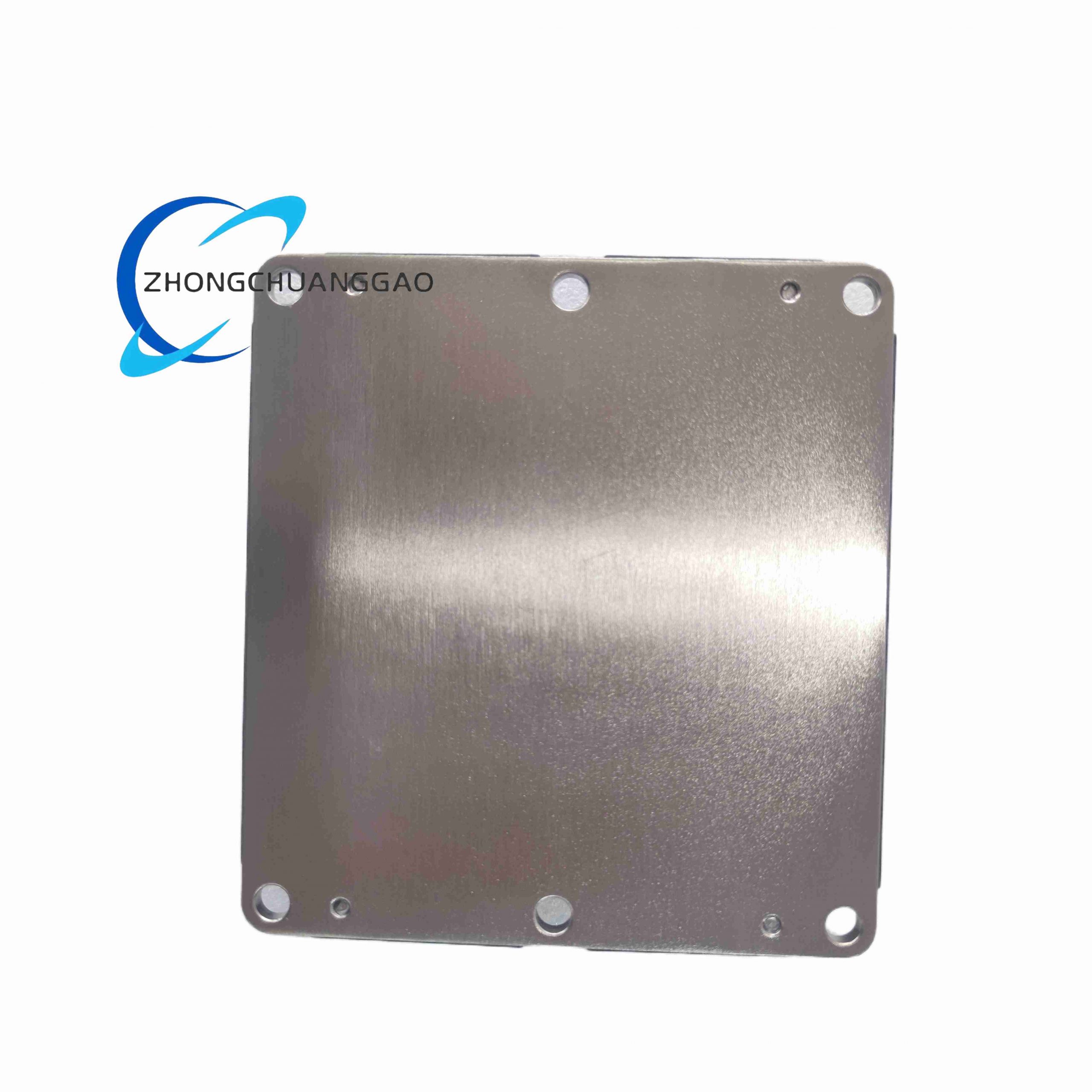
Rectangular flat press-fit high-power module structure, flat copper baseplate at the bottom fully attached to external heat sink for heat conduction. Two independent IGBT phase leg circuits integrated inside single sealed housing, separated by silicone gel insulation medium to avoid internal arc discharge under high voltage. Heavy-duty copper power terminals extend outward from the side of the module for direct busbar connection; small gate signal terminals arranged on the upper edge for gate drive board wiring. Four symmetric mounting holes distributed on four corners of the baseplate for uniform pressing force during installation to eliminate air gap between baseplate and heat sink. Internal DCB ceramic substrate completely isolates high voltage power circuit from metal baseplate, preventing electric leakage to cooling system. The sealed plastic shell prevents cooling water, dust and oil mist from penetrating internal chip area.
Working Principle
The module contains two independent IGBT power switches and two matching anti-parallel freewheeling diodes to form one complete single-phase bridge arm. External gate drive circuit sends +15V forward voltage to gate terminals to form conductive channel inside silicon IGBT chip, allowing large DC current to flow from collector terminal to emitter terminal for power energy conversion. When gate voltage switches to -15V, the conductive channel disappears instantly, cutting off main circuit current within microsecond level. Inductive load generated reverse current flows through parallel freewheeling diodes to avoid destructive voltage spike on IGBT chips. The heat generated by power loss during switching and conduction transfers from silicon chips through DCB ceramic substrate to copper baseplate, then dissipates into external water-cooled or air-cooled heat sink. Internal silicone gel insulates all live power components to avoid high voltage arc between internal circuits. The gate terminal built-in Zener diode clamps gate voltage within safe range to protect thin gate oxide layer from overvoltage breakdown.
Installation Requirements
- Install module flat on smooth water-cooled heat sink surface; surface flatness tolerance of heat sink must be less than 0.02mm, no scratches or deformation.
- Evenly coat 0.1–0.2mm thickness thermal conductive silicone grease between module baseplate and heat sink to eliminate air gap and reduce thermal resistance.
- Tighten four mounting bolts with torque wrench following diagonal cross sequence, standard torque value 25 N·m, over-tightening cracks ceramic substrate, insufficient torque causes heat dissipation failure.
- Power busbar connection torque for copper terminals: 30 N·m, use spring washer to prevent loose contact caused by thermal expansion and contraction.
- Gate control signal wiring must adopt shielded twisted pair cable, shield layer single-point grounded on gate drive board side, cable length limited within 1 meter to suppress switching noise interference.
- Cooling water for water cooling system requires deionized water with conductivity below 5μS/cm, inlet water temperature controlled between 25°C ~ 45°C, flow rate no less than 8 L/min per single module.
- Reserve minimum 100mm distance between adjacent FZ1200R12KF1 modules inside power cabinet to avoid mutual heat accumulation.
- Gate drive power supply must provide stable ±15V isolated power, independent from main high-voltage DC bus power supply.
Use & Maintenance Precautions
- Strictly forbid static touch gate signal pins without anti-static wristband; static electricity easily breaks thin gate oxide layer and permanently damages IGBT chips.
- Never operate the module without qualified heat sink installed; instant over-temperature will melt internal bonding wires and lead to module short-circuit failure.
- Do not exceed maximum junction temperature 150°C during continuous operation; long-term over-temperature sharply reduces service life of ceramic substrate and bonding wires.
- Check thermal conductive grease status every 12 months of continuous operation; replace aging dried grease to maintain heat dissipation efficiency.
- Inspect power busbar terminal torque every half year; thermal cycling will loosen bolts and cause contact overheating.
- Equip fast fuse and hardware short-circuit protection circuit on main DC bus; short-circuit duration exceeding 10μs will destroy IGBT chips.
- Avoid frequent overcurrent impact load operation, repeated heavy current surge accelerates bonding wire fatigue fracture.
- Store spare modules in sealed anti-static packaging under constant temperature dry environment, do not expose to humid air to prevent copper terminal oxidation.
- Do not cut open the plastic housing or remove internal silicone gel; housing damage will void manufacturer warranty and bring high voltage safety hazard.
- After power module failure replacement, test gate drive voltage waveform and short-circuit protection function before full-load operation of equipment.
Reviews
There are no reviews yet.