
Product Short Description
Product Overview
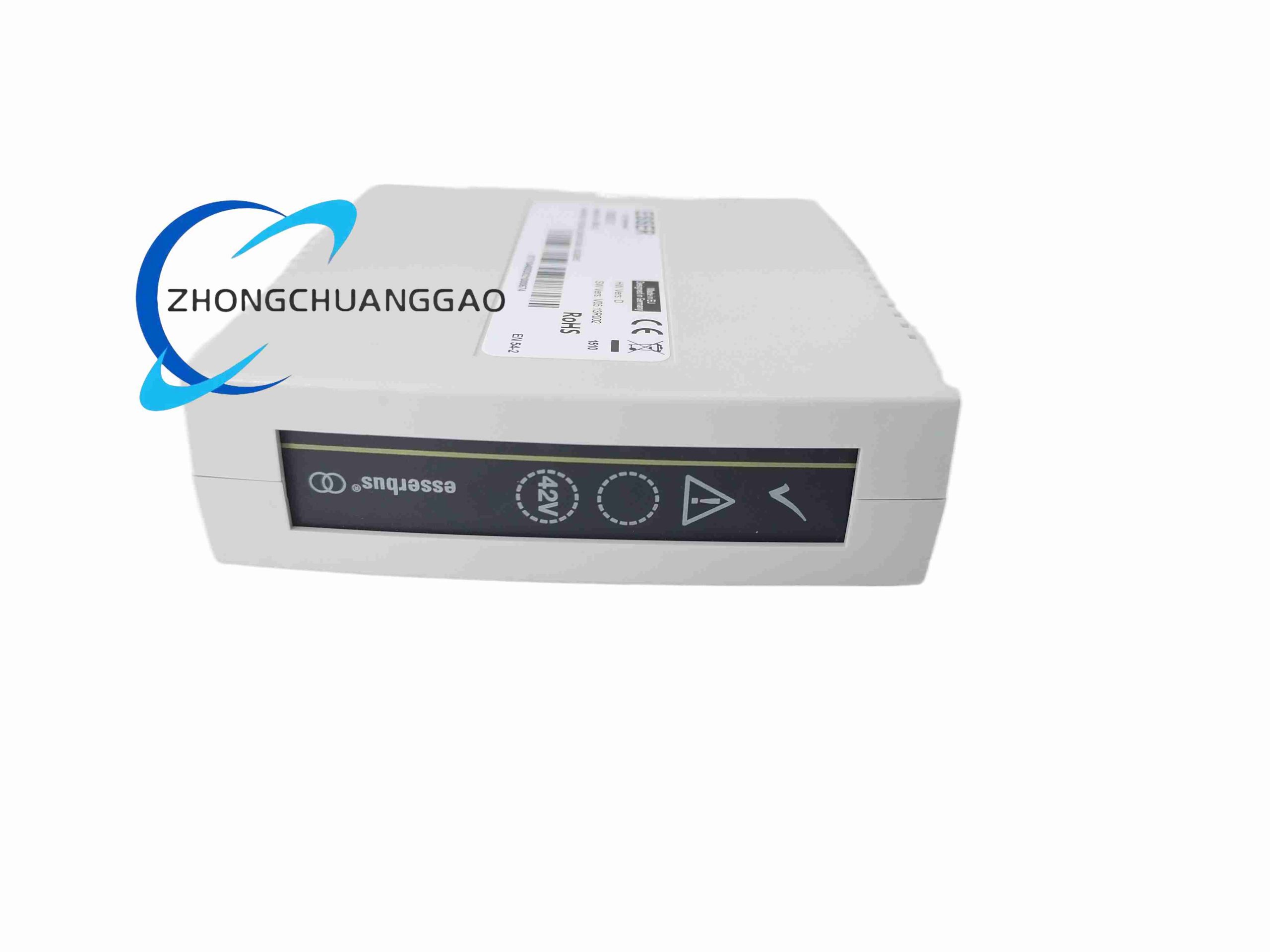
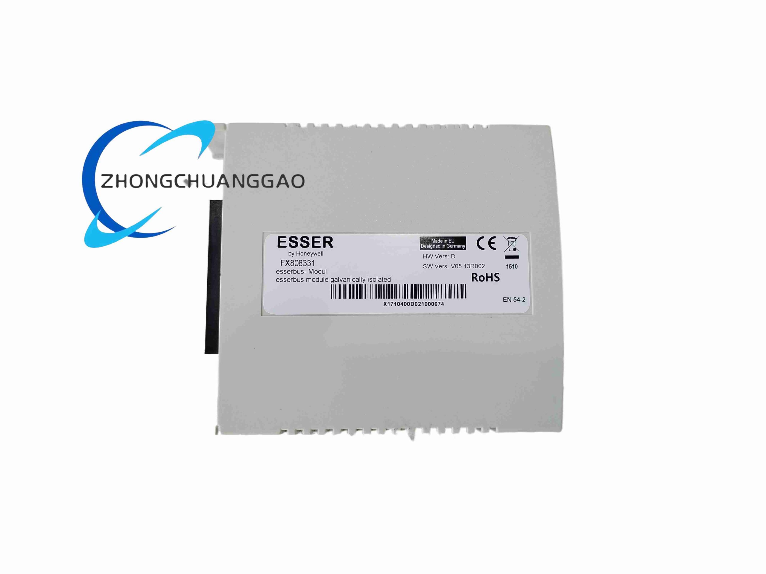
Intelligent fire alarm loop circuit board for Honeywell FlexES fire control panel, provides addressable fire detector communication bus drive, supports smoke detector, heat detector, manual call point, fire alarm sounder address signal collection and power supply output, realizes fire zone positioning, fault self-diagnosis and alarm linkage output.
Description
Technical Specifications
- Loop bus capacity: Single loop supports up to 127 addressable fire devices
- Loop bus output voltage: 24 V DC fire alarm rated power supply
- Loop communication protocol: Honeywell proprietary EDP addressable bus protocol
- Loop wiring mode: Two-wire non-polarized bus wiring
- Maximum single loop cable length: 3000 m with 1.5 mm² copper cable
- Operating temperature range: -10°C ~ +60°C
- Certification standard: VdS, EN 54 fire safety certification, CNBOP European fire standard
- Module size: Standard fire panel rack plug-in card
- Power consumption per loop: Max 12 W
Function Features
- Continuous loop bus impedance monitoring, automatic identification of open circuit, short circuit, ground leakage fault, accurate fault location address display on fire panel
- Class A (isolated redundant) and Class B (conventional) loop wiring mode configurable via panel software
- Individual address device self-diagnosis, reports smoke/heat detector contamination, device aging fault signal
- Emergency operation mode: Main CPU fault still maintains loop fire alarm signal collection and local sound-light alarm output
- Fire alarm zone partition function, each address device assigned independent zone code for fire positioning
- Built-in short-circuit isolation module, single segment bus short circuit does not affect normal operation of other address devices on loop
- Upload fire alarm, fault, isolation event data to building fire monitoring host via RS485 EDP communication interface
Application Scenarios
Commercial office building fire alarm control cabinet, shopping mall intelligent fire detection system, hotel fire safety monitoring, hospital ward fire alarm panel, factory workshop addressable smoke detection system, underground parking lot fire linkage control, school campus fire protection system.
Performance Parameters
- Bus communication polling cycle: ≤2 seconds full loop 127 device scan
- Short circuit isolation response time: ≤100 ms after bus short circuit occurs
- Fire alarm signal transmission delay: ≤300 ms from detector to fire panel
- Service life cycle: 10 years continuous operation without component replacement
- Insulation withstand voltage between loop bus and panel power supply: 1500 V AC
Material Composition
- Circuit board substrate: High anti-flame FR4 PCB with anti-corrosion surface coating
- Bus drive chip: Industrial grade communication transceiver chip with surge protection
- Short-circuit isolation components: PTC self-recovery fuse + thyristor surge suppressor
- Gold-plated rack connector for fire panel backplane bus connection
- Surface mount high temperature resistant electrolytic filter capacitors
Structural Characteristics
Horizontal rack plug-in circuit board, rear gold-plated backplane connector connected to fire alarm main control CPU and power supply, front panel loop bus wiring terminal block and status LED indicators (Loop Normal, Fire Alarm, Loop Fault, Isolation Active). Independent short-circuit isolation circuit distributed on each loop signal channel, integrated overvoltage protection circuit at bus wiring terminal inlet.
Working Principle
FX808331 loop card outputs 24V DC power supply and EDP address polling signal through two-wire loop bus to all connected addressable fire detectors and alarm devices. Each fire device carries a unique hardware address code; the loop card sequentially sends polling signals to each address point to collect real-time device status including normal standby, fire trigger, component fault, sensor contamination warning. Once smoke or heat detector captures fire characteristic signals, the device feeds back alarm data to the loop card within 300ms. The loop card forwards all alarm information to the fire control panel main CPU to activate local sound-light alarm and trigger linkage control of fire doors, smoke exhaust fans, fire extinguishing valves. The built-in impedance monitoring circuit continuously measures bus line resistance, automatically identifies open circuit, short circuit and cable ground leakage faults, and displays the exact fault address on the fire panel. When partial bus short-circuit happens, independent PTC isolation components cut off the faulty segment instantly to guarantee all other addressable devices on the loop work normally. Under main CPU failure emergency mode, the loop card retains independent signal collection logic to ensure fire alarm signal output without interruption.
Installation Requirements
- Install the plug-in card inside certified Honeywell FlexES fire control cabinet, insert firmly into designated loop slot and lock the metal fixing screw to avoid loose contact under vibration.
- Loop field wiring adopts 2-core fire-resistant shielded cable with cross-section 1.0–1.5mm²; cable laying must separate from high-voltage power cables with minimum 30cm spacing.
- Class A redundant wiring needs two independent cable routes for the same loop; Class B conventional wiring allows single cable layout.
- Each loop bus total load shall not exceed 127 addressable devices, strictly prohibit overloading to prevent communication delay and power supply insufficiency.
- Cabinet grounding bus must connect the shielding layer of all loop cables with single-point grounding, ground resistance controlled below 4Ω.
- Maintain cabinet internal temperature between -10°C ~ +60°C; install heating device for low-temperature outdoor cabinet application below 0°C.
- Leave 1 slot empty between two adjacent loop cards for heat dissipation, avoid stacking multiple high-power loop cards in concentrated area.
Use & Maintenance Precautions
- Cut off the whole fire panel main power before plugging or removing FX808331 card, live plugging will burn backplane communication chips.
- Inspect loop bus wiring insulation resistance every quarter, eliminate cable damage and water seepage timely to avoid ground leakage fault.
- Clean front panel terminals and indicator light dust every six months, dust accumulation causes poor contact and signal loss.
- Do not connect non-Honeywell third-party addressable fire equipment to the loop bus, incompatible protocols lead to frequent communication failure and missing fire alarm signals.
- After replacing smoke/heat detectors on site, re-scan the loop address via fire panel software to update device mapping data stored on FX808331.
- Replace internal aging filter capacitors every 8 years of continuous operation to prevent bus voltage fluctuation.
- Avoid chemical corrosive gas environment for fire cabinet placement; corrosive gas will corrode PCB traces and gold-plated connectors of the loop card.
- Conduct full fire simulation test every half year to verify loop alarm transmission speed and short-circuit isolation function of the module.
-500x500.jpg)
Reviews
There are no reviews yet.