
Product Short Description
Product Overview
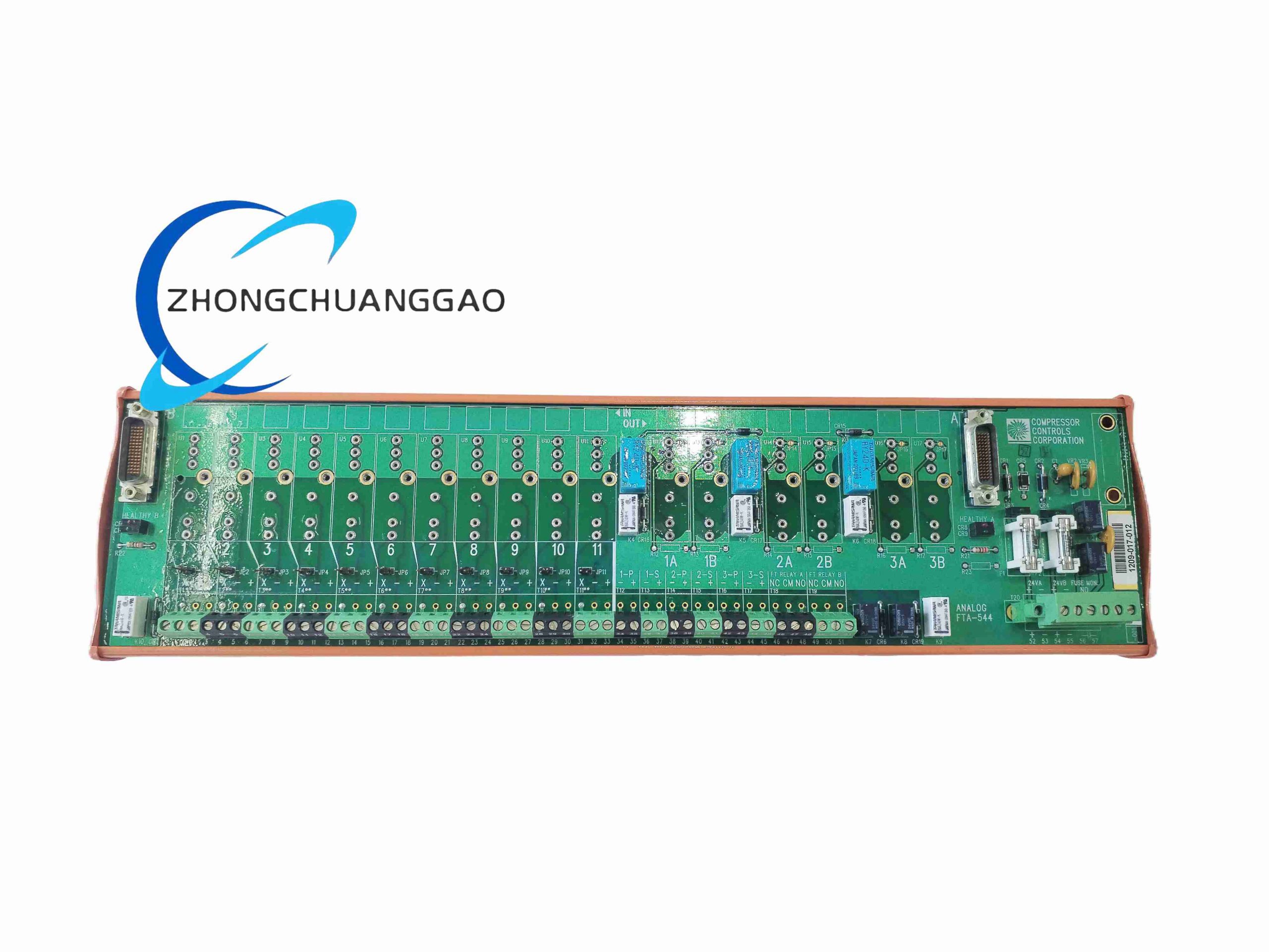
Dedicated field wiring terminal assembly matched with Honeywell FS-SDO-0824 safety output module, realizes separation between rack internal backplane circuit and field on-site wiring, provides surge suppression, short-circuit protection, easy wiring and maintenance interface for SIS safety system field loads.
Description
Technical Specifications
- Matching module: FS-SDO-0824 8-channel safety digital output module
- Wiring terminal quantity: 8 groups of load signal terminals + 2 groups of public power terminals
- Rated voltage: 24 V DC
- Single terminal maximum current: 0.6 A
- Built-in protection: TVS surge suppression diode, self-recovery fuse per channel
- Protection rating: IP20 (cabinet internal installation only)
- Mounting method: Standard 35 mm DIN rail mounting
- Dimensions: 110 mm × 75 mm × 32 mm
- Net weight: 0.08 kg
Function Features
- One-to-one channel signal mapping with FS-SDO-0824, clear channel number marking for easy troubleshooting
- Per-channel self-recovery fuse prevents field short circuit from damaging rack internal safety module
- Built-in bidirectional TVS transient voltage suppressor to absorb inductive load back EMF surge
- Spring-cage push-in wiring terminals, no screwdriver required for fast field cable connection
- Test point reserved on each channel terminal for multimeter signal measurement without wire disassembly
- Integrated cable strain relief clamp to avoid wire pulling damage terminal contacts
- Plastic housing with channel number silk-screen printing, convenient field wiring identification
- Daisy-chain power bus terminal for centralized 24V DC safety power distribution
Application Scenarios
Supporting wiring terminal for all Honeywell SIS safety output modules, deployed in oil & gas, petrochemical, chemical, power plant safety instrument control cabinets, connecting emergency shutdown valves, safety solenoid valves, fire alarm interlock relays.
Performance Parameters
- Self-recovery fuse trip current: 0.7 A per channel, automatic recovery after short circuit elimination
- Surge suppression voltage: 33 V DC clamping voltage
- Terminal wiring wire range: 0.5 mm² ~ 1.5 mm² solid copper cable
- Terminal contact resistance: ≤10 mΩ
- Vibration resistance: 10–100 Hz, 1.5 g without loose wiring
- Operating humidity: 5% ~ 90% RH non-condensing
Material Composition
- Terminal housing: UL94 V-0 flame retardant PA66 plastic
- Conductive terminal spring: High elasticity beryllium copper alloy with nickel plating anti-oxidation
- Surge protection components: Ceramic TVS diode, polymer self-recovery fuse
- DIN rail mounting clip: Spring steel galvanized anti-rust material
Structural Characteristics
Horizontal DIN rail mounting strip structure, upper row field wiring terminals, lower row internal ribbon cable socket connecting to FS-SDO-0824 module. Independent partition between each channel terminal to prevent inter-channel short circuit caused by wire stray contact. Integrated wire locking clamp on cable inlet to fix external field cables. Centralized public power bus bar for shared 24V DC power supply of all 8 channels.
Working Principle
Ribbon cable transmits 8-channel safety output signals from FS-SDO-0824 module to FTA-544 internal conductive busbars. Each channel busbar connects to independent spring terminal, series-connected self-recovery fuse and TVS surge protection device between busbar and field wiring terminal. When field load short circuit occurs, fuse disconnects channel circuit to protect the SIS module; inductive load reverse voltage surge is absorbed by TVS diode to avoid voltage spike damaging internal safety circuit. Test probes on each terminal directly conduct real-time signal measurement without disconnecting field cables.
Installation Requirements
- Mount on 35 mm standard DIN rail inside control cabinet, install within 0.5 m distance of matched FS-SDO-0824 module
- Internal ribbon cable supplied by Honeywell original factory, cannot replace with ordinary flat cable
- Field cable stripping length controlled at 6 mm, fully inserted into spring terminal without exposed copper wire
- Separate safety signal wiring and non-safety analog wiring with minimum 20 mm spacing inside cabinet
- Cabinet grounding bus connected to FTA metal mounting clip for anti-static shielding
- Leave 20 mm vertical space above and below terminal block for heat dissipation and wiring operation
Use & Maintenance Precautions
- Do not connect wire cross-section larger than 1.5 mm² to spring terminals, will cause loose contact
- Regularly check terminal spring elasticity every 6 months; aging springs lead to poor contact heating
- If self-recovery fuse repeatedly trips, inspect field cable short circuit or load overload fault first
- Do not disassemble internal plastic partition between channels, cross-channel short circuit risk will occur
- Avoid chemical solvent contact with plastic housing; solvent will cause plastic cracking and deformation
- Keep cabinet internal clean, dust accumulation on terminals leads to leakage current and signal deviation
-500x500.jpg)
Reviews
There are no reviews yet.