
Product Short Description
Product Overview
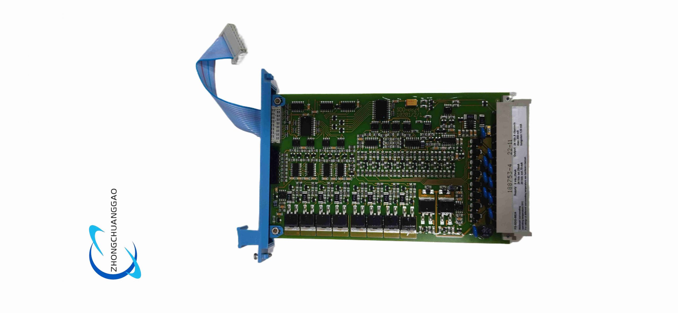
TÜV SIL-certified safety digital output module for Honeywell Safety Manager SIS control system, used to drive safety interlock actuators such as emergency shutdown valves, fire suppression equipment, safety trip relays in hazardous process industries. Adopts dual redundant circuit design to meet high safety integrity level requirements.
Description
Technical Specifications
- Number of output channels: 8 independent single-ended digital output channels
- Rated output voltage: 24 V DC nominal
- Single channel maximum load current: 0.55 A
- Total module maximum power dissipation: 6.1 W
- Safety certification: SIL 3, TÜV, CE, UL, FM, CSA
- Operating temperature range: -40°C ~ +85°C
- Signal bandwidth: 20 Hz (-3dB)
- Module size: 4 TE width, 3 HE height standard DIN rail rack module
- Net weight: 0.12 kg
- External power supply requirement: 24 V DC ±5% isolated safety power
Function Features
- Dual cross-check safety circuit architecture, any single component fault will force output to safe de-energized state
- Independent channel diagnosis circuit, real-time monitoring of open circuit, short circuit, overload of each output load
- Built-in hardware watchdog timer; communication loss between module and CPU triggers automatic safety trip within 10 ms
- Each channel supports configurable fail-safe mode (de-energized safe state by default)
- Short-circuit current limiting protection per channel, avoids module burnout caused by load short
- Hot-swap support, module replacement without system full power cut-off
- LED status indicator for each channel: power normal, channel active, channel fault
- Digital fault signal uploaded to SIS CPU via backplane bus for upper system fault recording
Application Scenarios
Oil & gas upstream/downstream emergency shutdown systems, petrochemical reactor safety interlock, chemical plant toxic gas release protection, power plant boiler safety trip, refinery fire suppression control, pharmaceutical hazardous production line safety instrument systems.
Performance Parameters
- Safety fault response time: ≤10 ms communication loss trip
- Channel isolation voltage: 500 V AC between adjacent channels
- MTBF (Mean Time Between Failures): ≥1,200,000 hours under rated operating conditions
- Maximum switching frequency of output channels: 10 Hz
- Electrostatic discharge immunity: ±8 kV contact discharge, ±15 kV air discharge
- Surge withstand capability: ±2 kV power line surge
Material Composition
- Module housing: Flame retardant black PA66 plastic, UL94 V-0 fire resistance grade
- Circuit substrate: High reliability FR4 PCB with heavy copper traces for high current output
- Power switching device: Industrial-grade optocoupler isolated power MOSFET
- Backplane connector: Gold-plated phosphor bronze terminal pins for stable long-term contact
- Internal insulating spacer: High temperature resistant polyimide film
Structural Characteristics
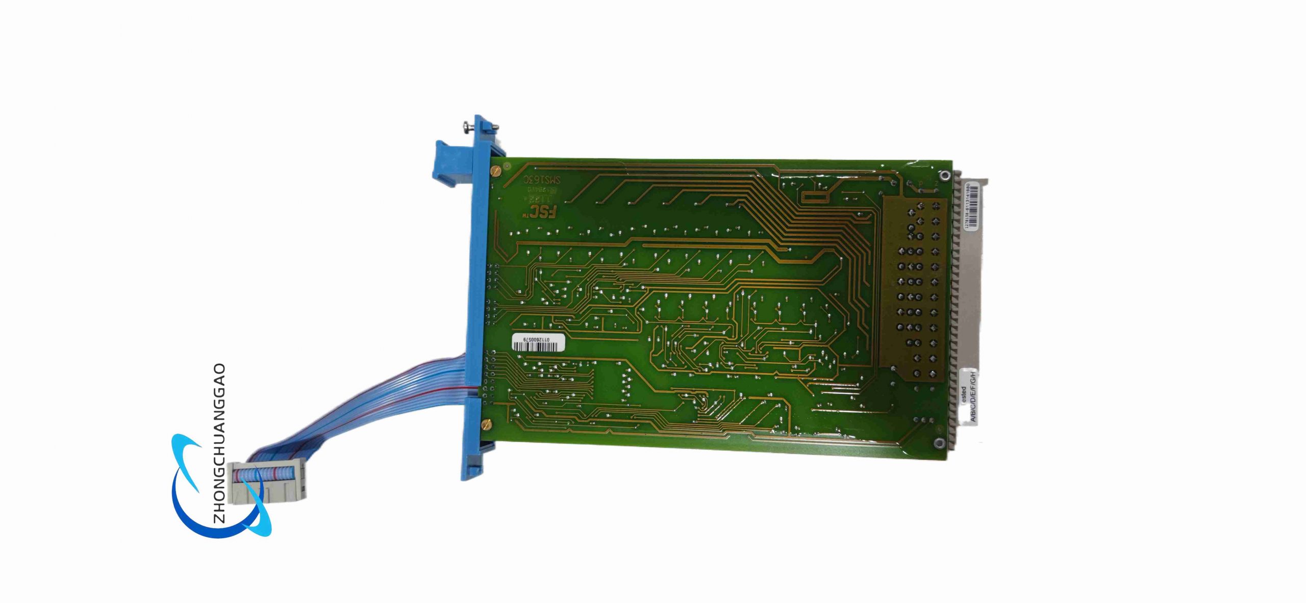
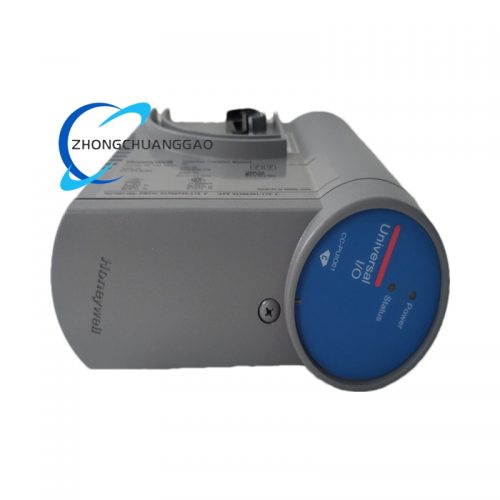
Standard Eurocard rack-mounted plug-in module, left side blue plastic pull tab for convenient extraction. Front panel with 8 groups of channel LED indicators and module power LED. Rear gold-plated backplane bus connector for communication and power supply with SIS rack. Internal circuit divided into isolated power zone, safety logic zone, output drive zone with physical isolation partitions to prevent cross-channel interference. Spring terminal wiring interface on front for field load wiring.
Working Principle
Receives safety logic command signals from SIS main CPU via rack backplane bus. Internal dual redundant logic processing circuits synchronously analyze commands; only when both redundant circuits output consistent valid signal will the corresponding channel MOSFET switch turn on to energize field safety actuator. Continuous real-time monitoring of each channel load voltage and current by diagnostic circuit; once abnormal open/short/overload detected, immediately cut off channel output and lock fault state. If CPU communication interrupts, hardware watchdog forces all 8 channels to de-energized safe state to eliminate process hazard risk.
Installation Requirements
- Install inside Class 1 Div 2 or Zone 2 hazardous area certified control cabinet, cabinet temperature maintained within -40 ~ +70°C long-term operation
- Field load wiring must use 18–22 AWG shielded twisted pair cable, cable length limited to maximum 50 m per channel
- Safety power supply for module must be isolated redundant DC power unit, separate from non-safety control power
- Leave minimum 1 TE empty slot between adjacent high-power modules for heat dissipation
- Cabinet ventilation fan required if rack internal temperature exceeds 60°C
- Cabinet unified protective ground with copper busbar, module ground terminal connected to ground bus
- Wiring terminals tightened with torque screwdriver at 0.8 N·m standard torque to prevent loose contact heating
Use & Maintenance Precautions
- Strictly prohibit connecting inductive loads without freewheeling diode; inductive back EMF will damage output MOSFET
- Do not exceed single channel 0.55 A load current; overload triggers permanent channel lock fault
- Perform full channel diagnostic test every 3 months of continuous operation to verify fault detection function
- Only original Honeywell replacement modules can be used; third-party modules invalidate SIL safety certification
- Do not disassemble module housing; internal safety circuit tampering will destroy SIL certification integrity
- Avoid placing rack near high-power frequency converters, high-voltage contactors to reduce electromagnetic interference
- Store spare modules in low-humidity constant temperature cabinet with anti-static packaging
Reviews
There are no reviews yet.