
Product Short Description
Product Brief Introduction
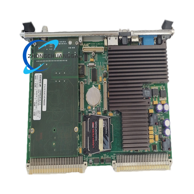
IS215UCVEM08 is the core master CPU controller board for GE Speedtronic Mark VI gas/steam turbine distributed control system, belonging to EM enhanced environmental series optimized for medium-harsh industrial working conditions. It executes all turbine closed-loop control logic, synchronizes all rack I/O terminal boards, processes real-time operating data, handles human-machine interface communication and remote plant monitoring transmission.
Description
Core Technical Specifications & Performance Parameters
- Processing & Memory Hardware
Industrial real-time multi-core processor; onboard battery-backed NVRAM for control parameter retention; industrial flash storage for firmware and control logic program
- Integrated Communication Interfaces
- 1 × 10/100 Mbps Ethernet TCP/IP port for plant SCADA system connection
- 2 × RS-232C serial COM ports for local debugging terminal connection
- SVGA video monitor port for GE proprietary on-site diagnostic display
- PS/2 keyboard & mouse interface for local parameter modification
- Proprietary high-speed backplane bus interface for rack internal I/O data exchange
- Power Supply & Backup
Onboard replaceable lithium coin backup battery (10-year service life) for clock and parameter memory retention; rack supplied 24 VDC logic power input
- Environmental Operating Range
Operating temperature: -30 °C ~ +75 °C; storage temperature: -40 °C ~ +85 °C; IP54 protection grade via full PCB conformal coating
- Certifications & Compatibility
UL/cUL hazardous location certification; fully compatible with Mark VI system firmware version 6.1 and above, backward compatible with IS215UCVGM standard controller series
- Physical Dimension & Weight
Single-slot VME-style rack PCB card: 340 mm (height) × 48 mm (width) × 210 mm (depth); net weight 2.1 kg
Material Composition & Structural Features
- PCB substrate: Thick copper FR4 circuit board, double-layer conformal acrylic coating resistant to salt mist, moisture and industrial chemical vapor
- Mechanical frame: Die-cast aluminum alloy edge reinforcement bracket to absorb mechanical vibration from turbine foundation
- Connector assembly: Gold-plated edge backplane connector for stable high-speed data transmission under vibration; rear panel sealed communication port connectors with dust-proof rubber gaskets
- Indication system: Three front panel multi-color LED indicators for power status, backplane bus communication fault, system run/stop state
- Battery compartment: Sealed plastic slot with anti-vibration lock for backup lithium battery, easy field replacement without full system power down
Working Principle
Receives all sensor and trip signal data transmitted from IS200 series terminal boards via rack backplane bus at fixed 1 ms real-time scan cycle. Internal real-time operating system executes pre-programmed turbine control logic algorithms (speed PID control, exhaust temperature limit protection, generator voltage regulation, startup/shutdown sequential logic). Calculates output control commands and sends back to I/O terminal boards to drive fuel valves, cooling air actuators and generator excitation systems. Simultaneously packages unit operating data through Ethernet port to plant SCADA monitoring system; stores all fault event records in non-volatile memory for post-failure analysis. Onboard SVGA and serial ports support local real-time data viewing and logic program download/modification.
Application Scenarios
- Land-based heavy-duty gas turbine power generation plants
- Steam turbine combined-cycle power station main control racks
- Onshore natural gas pipeline compressor drive turbine control systems
- Coastal refinery and petrochemical process turbine units with high humidity & salt air
- High-altitude hydroelectric auxiliary turbine control cabinets
Installation Requirements
- Install in primary master CPU slot of Mark VI standard 19-inch control rack, secure with dual locking screws to resist continuous vibration
- All communication cables must be industrial shielded Ethernet and RS-232 cables, connectors tightened with locking nuts to prevent loose contact
- Rack forced air cooling airflow must maintain card surface temperature below 70 °C; blockage of air inlet/outlet strictly prohibited
- Maintain minimum 20 mm clearance above and below controller card for heat dissipation
- System ground bus resistance ≤ 1 Ω to eliminate common-mode communication interference
Operation & Maintenance Precautions
- Complete full system power shutdown before replacing onboard backup lithium battery to avoid parameter data loss
- Only download control logic programs via GE ToolboxST dedicated software; incompatible third-party editing tools will cause system crash
- Conduct battery capacity inspection every 2 years; replace battery when low-battery LED warning activates
- Never remove PCB conformal coating; use dry compressed air to clear accumulated dust on circuit surface
- After controller card replacement, execute full turbine logic simulation test before unit live startup
Reviews
There are no reviews yet.