
Product Short Description
Product Brief Introduction
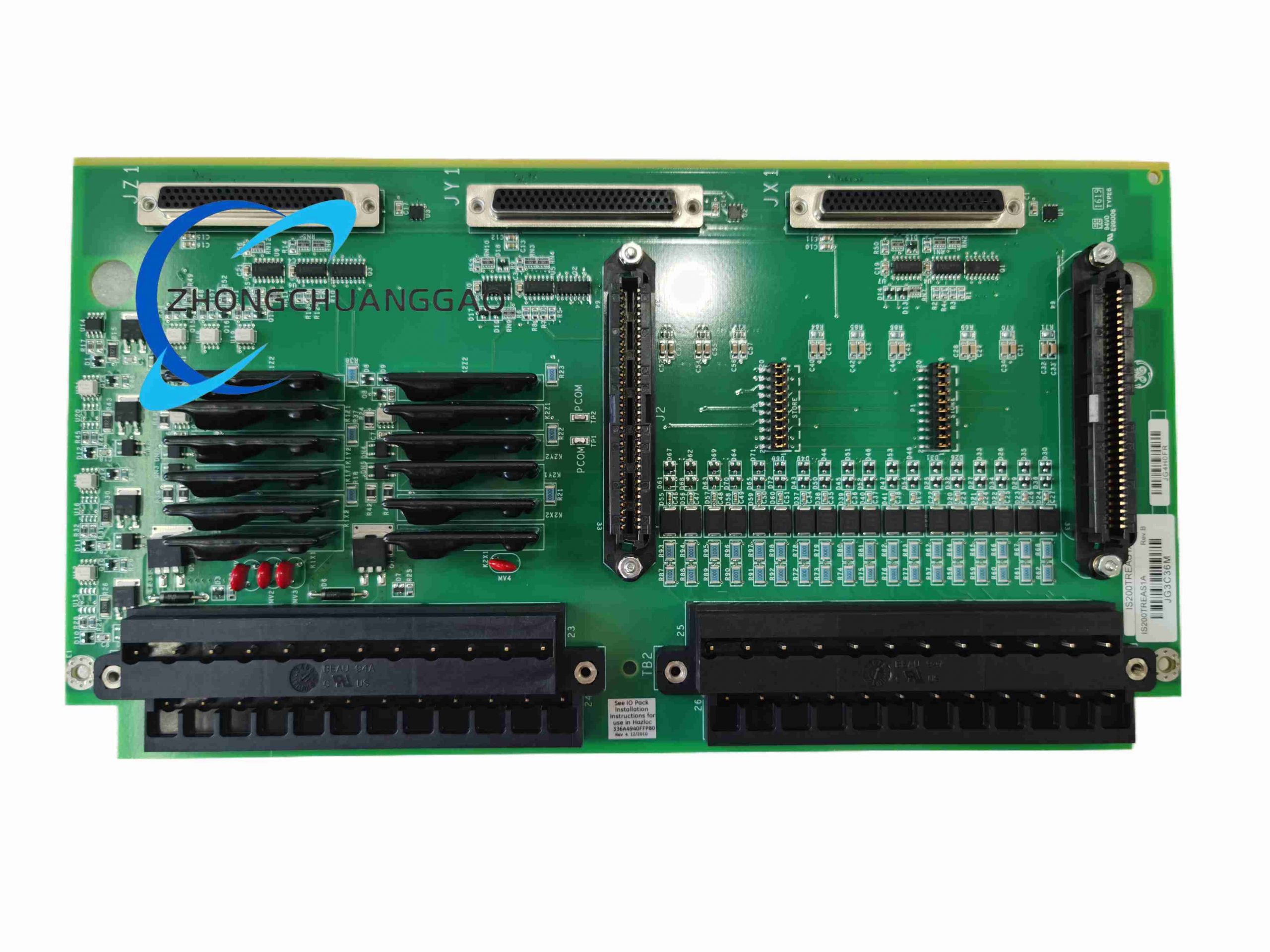
Manufactured by GE Vernova for Speedtronic Mark VIe distributed turbine control system, IS200TREAS1A is dedicated emergency trip signal terminal and signal conditioning board for aeroderivative gas turbine generator sets. It collects turbine speed pulse signals, emergency shutdown discrete inputs, thermocouple/RTD temperature analog signals, provides galvanic isolation, signal filtering and level conversion, transmits conditioned data to Mark VIe PPRO/YPRO I/O controller packs via proprietary backplane bus.
Description
Core Technical Specifications & Performance Parameters
- Signal Input Channels Configuration
- 9 tooth-wheel pulse speed sensing inputs (3 groups X/Y/Z triple redundant turbine speed measurement)
- 16 configurable analog signal inputs: K/J/E type thermocouple, Pt100 RTD, 4–20 mA industry standard analog
- 48 discrete emergency trip digital input terminals (24 VDC / 125 VDC dual voltage compatible)
- Electrical Isolation Performance
1500 VAC continuous galvanic isolation between field wiring side and control backplane side, suppress EMI/RFI interference from high-power turbine excitation circuits
- Backplane Communication Interface
Proprietary IS200 high-speed differential backplane bus, real-time data refresh cycle 2 ms
- Auxiliary Operating Power
Nominal 125 VDC input, wide operating range 85 VDC – 150 VDC
- Environmental Performance Grade
Standard operating temperature range: -20 °C ~ +70 °C; certified Class I Div 2 hazardous area, ATEX Zone 2
- Reliability Index
Calculated MTBF > 250,000 operating hours under rated industrial environment
- Physical Size & Weight
Rack-mounted single slot PCB assembly: 318 mm (height) × 45 mm (width) × 200 mm (depth); total net weight 1.8 kg
Material Composition & Structural Features
- Main circuit substrate: High TG FR4 industrial PCB with full acrylic conformal coating for moisture and salt mist resistance
- Terminal connectors: Two sets of 24-point pluggable barrier terminal blocks + 48-point Euro-style spring clamp terminals, tin-plated copper contact pins
- Enclosure & mounting: Aluminum alloy reinforcing frame for anti-vibration protection, integrated card edge connector for Mark VIe system rack backplane insertion
- Internal components: Precision instrumentation amplifiers, surge suppression TVS diodes, low-pass LC signal filter circuits, redundant signal sampling chips
- Indicator structure: Front panel multi-color LED status lights for power, bus communication, trip signal trigger and board fault diagnosis
Working Principle
Field sensor raw signals (speed pulse, temperature analog, emergency shutdown dry contacts) enter the board’s terminal blocks, first pass through surge suppression and EMI filter circuits to eliminate high-voltage spikes and electromagnetic noise. Isolation amplifiers separate field high-voltage loops from low-voltage control logic circuits, convert all analog signals to standardized digital sampling values, convert pulse tooth-wheel signals to real-time turbine RPM data. Processed digital data is packaged and transmitted over backplane bus to central UCV controller; when emergency trip signal is detected, board sends hardwired fast shutdown interrupt signal with 1 ms response latency to trigger turbine fuel valve cut-off protection logic.
Application Scenarios
- Aeroderivative gas turbine combined-cycle power generation units
- Industrial mechanical drive gas compressors powered by GE aeroderivative turbines
- Distributed on-site power plants, offshore platform turbine generator control cabinets
- Cogeneration heat & power industrial facility turbine safety monitoring systems
Installation Requirements
- Install exclusively inside GE Mark VIe standard 19-inch vertical control rack, fixed via rack card guides with locking screw to resist turbine base vibration
- All field signal cables must be shielded twisted pair, shield grounded at cabinet single PE point, no multi-point grounding
- Maintain minimum 15 mm vertical gap between adjacent rack cards for forced air cooling airflow
- Only perform hot-swap replacement under turbine partial load non-critical maintenance mode; full emergency trip test required after card replacement
- Rack cooling air inlet temperature cannot exceed 55 °C sustained
Operation & Maintenance Precautions
- Strictly avoid short-circuit between 125 VDC power terminals and signal input terminals during wiring; short-circuit will burn isolation amplifier circuits
- Use GE official ToolboxST configuration software only for signal channel parameter calibration; third-party software not supported
- Execute full trip signal loop inspection every 6 months during unit scheduled outage
- Do not remove conformal coating on PCB surface for cleaning; compressed air (dry, <2 bar) only for dust removal
- If LED fault alarm activates, isolate corresponding input channel first before disassembly inspection
Reviews
There are no reviews yet.