
Product Short Description
Product Brief
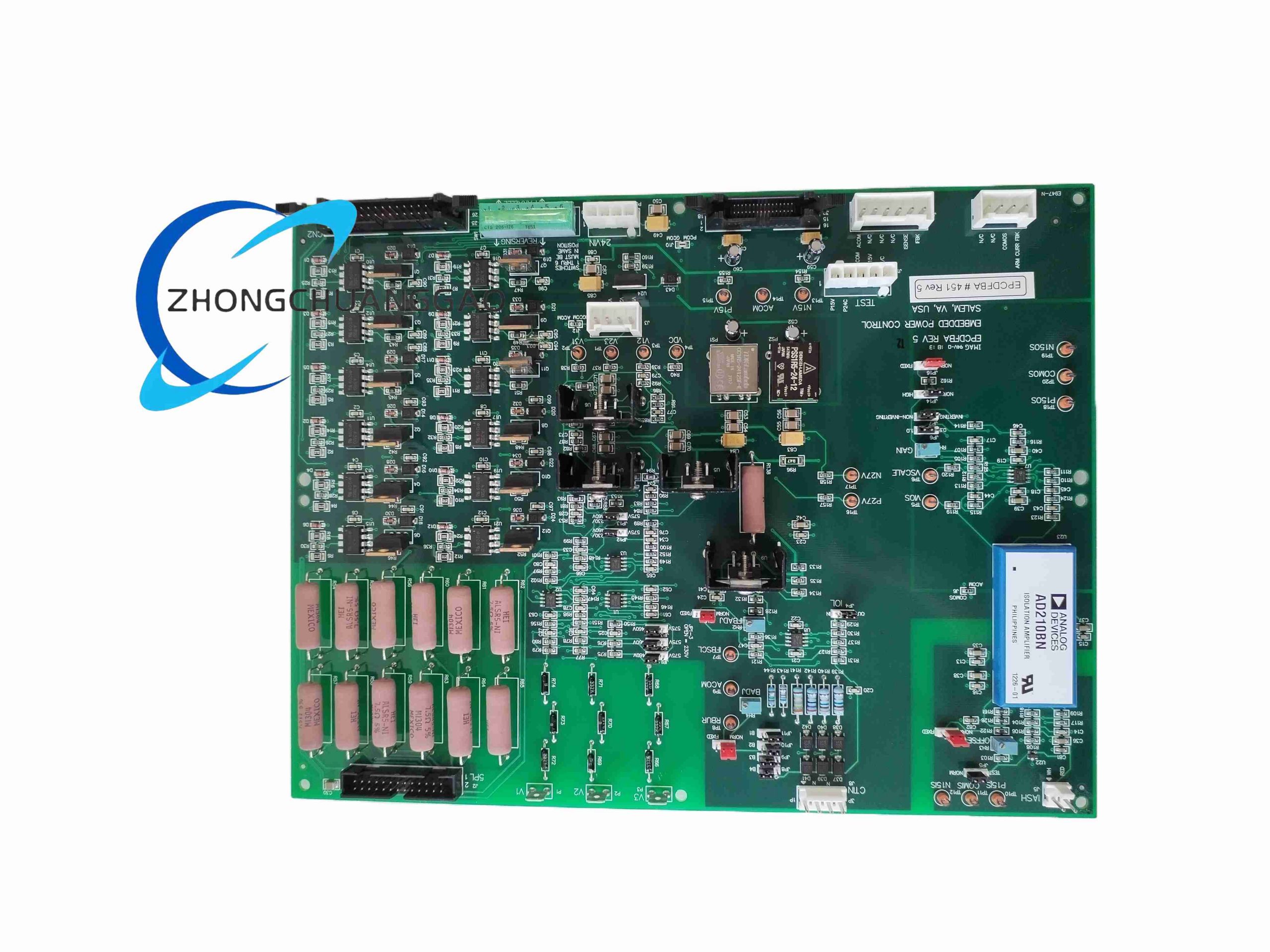
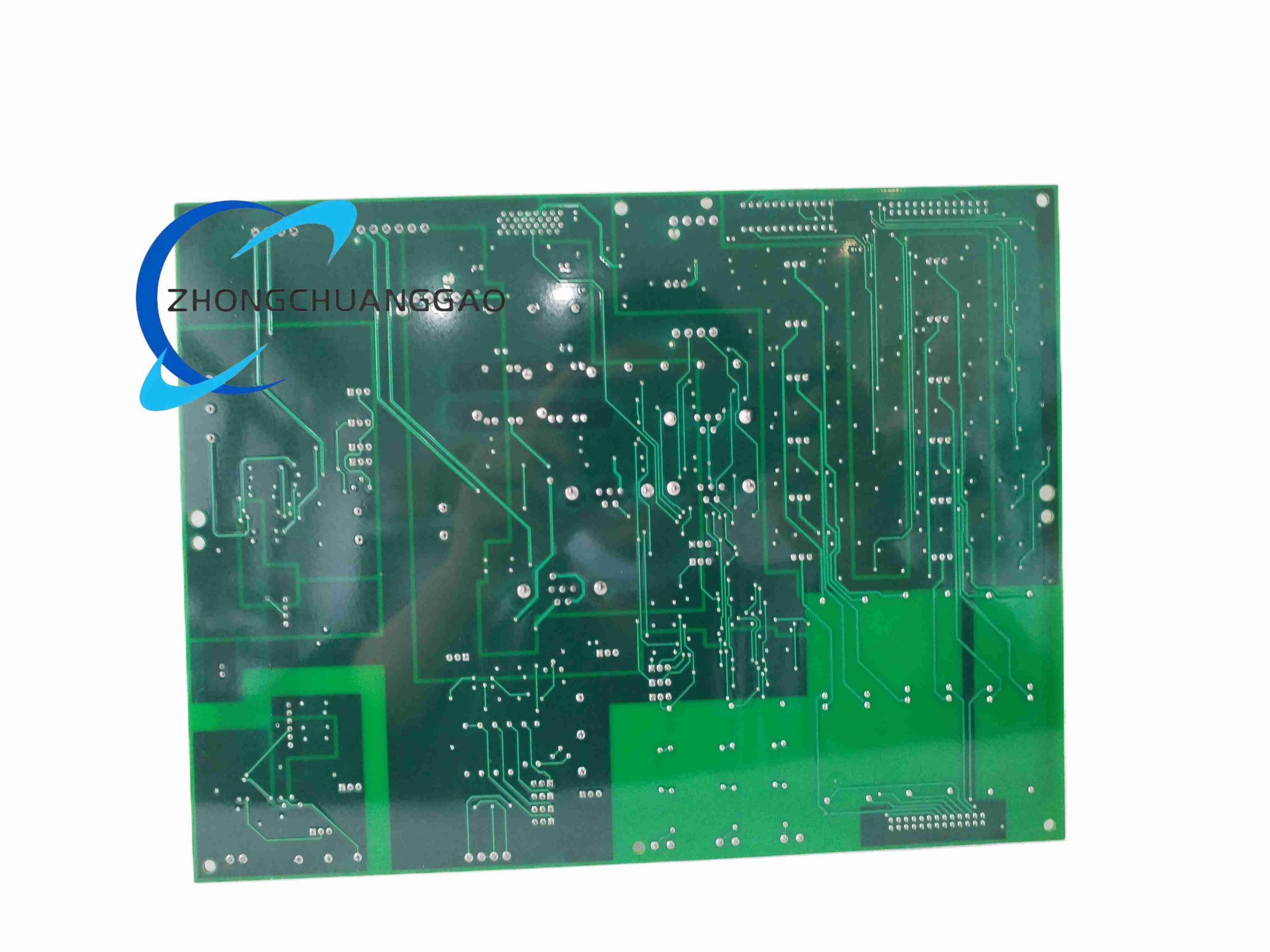
EPCDFBA is a custom coded embedded single-board computer developed for dedicated industrial distributed field bus control applications, integrated with on-board analog/digital I/O and multi-protocol communication transceivers for compact cabinetless automation deployment.
Model Series
Custom EPC Custom Embedded Controller Series, model designation EPCDFBA for field bus automation variant
Description
Technical Specifications
- Core Processor: 32-bit ARM Cortex-A9 dual-core CPU, operating clock 1.0 GHz
- On-Board RAM: 1 GB DDR3 industrial-grade low-temperature memory
- Storage: 8 GB SLC industrial flash memory chip
- Operating Supply: 12–24 VDC wide range input, reverse polarity protection
- Digital I/O: 16 isolated digital inputs (24 VDC logic), 16 open-collector digital outputs
- Analog Interfaces: 4-channel 0–10 V analog input, 2-channel 4–20 mA analog output
- Field Bus Interfaces: On-board CAN 2.0B, RS485 Modbus RTU, Ethernet IP
- Operating Temperature: -40 °C to +75 °C
- Protection Grade: IP00 bare board, requires external enclosure
Functional Features
- Pre-compiled real-time Linux industrial operating system with 1 ms hard real-time scheduling
- Native support for industrial field bus communication protocols without external expansion modules
- On-board hardware watchdog timer with automatic system reset function
- Built-in analog signal low-pass filtering to eliminate industrial electromagnetic interference
- Configurable I/O logic via offline PC software or remote Ethernet parameter upload
- On-board RTC clock with backup lithium coin cell for persistent timestamping
- Fault detection circuit for short-circuit and over-current output channel conditions
Performance Parameters
- Real-time task scheduling latency: ≤ 1 ms
- Flash memory data retention: ≥ 15 years at standard storage temperature
- RTC backup battery service life: Minimum 5 years continuous operation
- Maximum communication bus refresh rate: 100 Hz for Modbus RTU data transmission
- Digital input response speed: 20 μs minimum trigger detection
Material Composition
- Main PCB substrate: FR4 high TG flame retardant circuit board, 1.6 mm thickness
- Processor package: Industrial ceramic packaged ARM CPU with wide temperature tolerance
- Communication transceivers: Isolated optocoupler integrated bus driver ICs
- Passive components: High-temperature tantalum capacitors, metal film precision resistors
- Connector terminals: Gold-plated copper pin headers for long-term vibration resistance
Structural Characteristics
- Compact bare-board dimensions: 120 mm (width) × 85 mm (height) × 18 mm (depth)
- All I/O and communication connectors aligned on single board edge for unified wiring
- Integrated isolated DC-DC power conversion circuit on single PCB layer
- Screw mounting holes at four board corners for secure chassis installation
Working Principle
DC input power passes through reverse polarity and overvoltage protection circuits to supply the isolated DC-DC converter, which generates regulated core logic voltage for the dual-core ARM processor. All analog and digital input signals pass through optocoupler isolation circuits before being sampled by the CPU. Processed control logic signals drive isolated output circuits, while field bus transceivers facilitate bidirectional data exchange with upper-level HMI and PLC systems. The hardware watchdog continuously monitors CPU heartbeat signals to execute full system reset upon software crash.
Advantage Highlights
- Ultra-wide operating temperature range supporting outdoor and heavy industrial cabinet installation
- All-in-one integrated I/O and multi-protocol bus design eliminates external expansion hardware
- Hard real-time operating system meets high-speed motion and process control timing requirements
- SLC industrial flash memory eliminates data corruption risk under power fluctuation
- Compact bare-board size enables integration into small machinery control housings
- Full galvanic isolation between power, signal and communication circuits prevents ground loop faults
Applicable Industries
Factory automation, packaging machinery, hydraulic control systems, material handling equipment, environmental monitoring stations, smart energy distribution equipment, portable industrial test instruments
Installation Requirements
- Install inside sealed IP54 minimum rated metal plastic enclosure to prevent dust and moisture ingress
- Mount board with minimum 30 mm surrounding clearance for passive heat dissipation
- Separate high-current power wiring and low-level analog signal wiring with physical partition barriers
- Install transient voltage surge suppression module at 12–24 VDC power input terminal
- Secure board via all four corner mounting screws to resist industrial equipment vibration
Operation Precautions
- Never operate bare PCB without protective enclosure in dusty, humid or corrosive gas environments
- Replace RTC backup lithium cell every 5 years to avoid timestamp data loss
- Do not connect analog signal wiring in parallel with high-frequency inverter power cables
- Limit continuous output channel load current to rated maximum to prevent PCB trace burnout
- Complete full system firmware backup before executing configuration parameter modifications
- Avoid static electricity discharge to PCB surface; wear anti-static wrist strap during maintenance
Reviews
There are no reviews yet.