
Product Short Description
Product Introduction
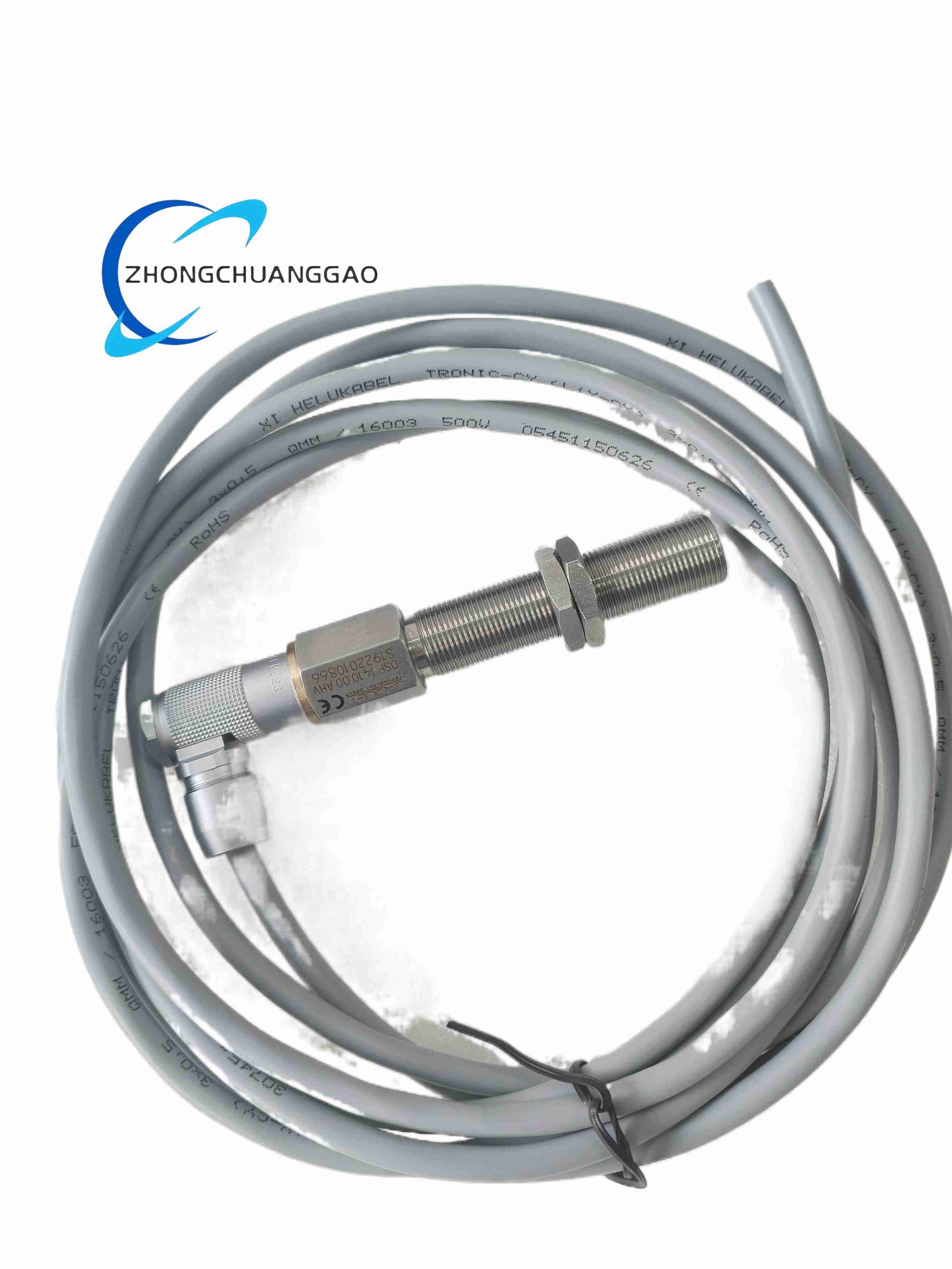
Full metal encapsulated non-contact variable reluctance sensor integrated assembly, model DSF1410.00 AHV dedicated for high-temperature rotating equipment rotational speed measurement and mechanical vibration signal collection. Generates analog sine-wave pulse signals proportional to rotating target gear tooth passing frequency, used for engine overspeed protection, turbine rotation closed-loop control and mechanical fault vibration monitoring in power generation and marine engine systems.
Description
Material Composition
- External sensing probe housing: High-temperature 316L stainless steel seamless tube
- Internal magnetic core: High-permeability soft ferrite magnetic pole
- Induction coil winding: High-temperature polyimide insulated copper magnet wire
- Encapsulation filling material: High-temperature inorganic ceramic potting compound
- Cable outer sheath: Fluoropolymer (FEP) heat-resistant anti-oil corrosion cable jacket
- Connector assembly: Nickel-plated stainless steel circular threaded waterproof connector
- Sealing components: High-temperature fluorine rubber O-ring gaskets
Structural Features
- Cylindrical single-body fully hermetically encapsulated probe structure, zero internal air cavity
- Threaded external mounting shank for direct screwing into equipment sensor mounting boss
- Integrated high-temperature flexible signal cable with factory crimped waterproof circular connector
- Variable reluctance magnetic induction core positioned at probe front tip for close-range gear tooth detection
- Multi-layer ceramic potting eliminates internal coil vibration friction damage under high mechanical vibration
- Complete corrosion-resistant stainless steel outer body resistant to salt fog, hydraulic oil and engine fuel vapor environments
Technical Specifications
- Full Model Code: DSF1410.00 AHV
- Working Sensing Principle: Variable reluctance magnetic induction (no external power supply required)
- Minimum Detectable Target Gear Tooth Speed: 10 RPM
- Maximum Continuous Operating Rotational Speed: 25,000 RPM
- Probe Front Tip Operating Temperature Range: -40 ℃ ~ +180 ℃
- Signal Cable Long-Term Temperature Tolerance: -40 ℃ ~ +150 ℃
- Recommended Air Gap Between Probe Tip and Gear Tooth Surface: 0.5 mm ~ 1.5 mm
- Output Signal Waveform: Sine wave alternating voltage signal
- Peak Output Voltage Amplitude (1 mm air gap, 100 teeth gear, 3000 RPM): ≥ 1.2 Vpp
- Sensor Internal Coil DC Resistance Standard Value: 220 Ω ± 10% at 25 ℃
- Shock Resistance Rating: 50 g peak mechanical shock per IEC 60068-2-27
- Vibration Resistance Standard: IEC 60068-2-6, 10–2000 Hz, 10 g continuous vibration
- Ingress Protection Grade: IP68 full waterproof and dustproof after connector assembly
- Probe Outer Diameter: M14 × 1.5 mounting thread
- Standard Factory Cable Length: 3 meters (custom length available upon order)
- Certifications: CE, marine DNV classification certification, power plant functional safety overspeed monitoring certification
Function Features
- Passive variable reluctance design requiring no external excitation power supply; operates reliably in equipment with limited auxiliary power layout
- Dual signal output capability: rotational speed pulse frequency signal for rotation speed calculation, sine wave amplitude fluctuation signal for mechanical vibration monitoring
- Ultra-wide high-temperature working range adapts to gas turbine, diesel engine exhaust side and hot rotating machinery mounting positions
- IP68 fully sealed stainless steel probe body resists immersion, engine oil, fuel, salt fog and corrosive industrial gas erosion
- High shock and vibration resistance withstands continuous mechanical oscillation of internal combustion engines and steam turbine shafts
- Wide air gap tolerance range allows minor installation dimensional deviation without signal loss
- Single sine-wave analog output compatible with all mainstream Jaquet speed monitoring relays, PLC analog input modules and vibration data acquisition systems
- Ceramic full encapsulation prevents coil winding short-circuit failure caused by long-term high-temperature thermal expansion and contraction
- Standard M14×1.5 metric mounting thread matches universal rotating machinery sensor mounting boss specifications
- Long service life with zero wearing moving parts; non-contact detection eliminates mechanical abrasion failure modes
Working Principle
The sensor internal soft ferrite magnetic core forms a permanent magnetic field at the front probe tip. When ferromagnetic gear teeth rotate and pass the probe sensing surface, the magnetic flux density passing through the induction coil cyclically increases and decreases with tooth and gap alternation. Periodic magnetic flux variation induces alternating sine-wave voltage signal in the copper coil winding following Faraday’s law of electromagnetic induction. The frequency of output sine wave directly corresponds to gear rotational speed, while minor amplitude modulation of the sine waveform reflects micro-vibration of the rotating shaft and gear assembly. Inorganic ceramic potting compound fixes the coil and magnetic core rigidly inside the 316L stainless steel housing to eliminate internal component friction damage under vibration. Fluoropolymer cable and fluorine rubber sealing maintain insulation integrity under continuous high-temperature exposure, and the threaded metal connector prevents liquid and particulate ingress into signal wiring terminals. No internal moving components ensure maintenance-free long-term operation.
Advantage Highlights
- Passive power-free design eliminates risk of auxiliary power circuit failure affecting overspeed safety protection loops
- Industry-leading +180 ℃ probe tip temperature rating enables installation at hot section of gas turbines and heavy-duty diesel engines
- IP68 hermetic sealing supports installation in splash-prone engine rooms, offshore marine machinery and outdoor power generation equipment
- Dual speed + vibration signal output realizes two-condition monitoring with single sensor, reducing installation quantity and wiring cost
- Ultra-high vibration and shock resistance meets strict marine engine and power turbine operating environment standards
- Standard M14×1.5 mounting thread universal for most industrial rotating machinery retrofitting without custom machining
- Non-contact detection design achieves infinite theoretical mechanical service life with no wear components
Applicable Industries
Marine diesel main engine overspeed protection, heavy-duty gas turbine speed monitoring, steam turbine generator shaft condition monitoring, locomotive diesel engine control, offshore platform generator sets, industrial reciprocating compressors, large ventilation fan vibration monitoring, hydroelectric turbine rotational safety interlock systems
Installation Requirements
- Screw DSF1410.00 AHV probe into equipment M14×1.5 sensor mounting boss with calibrated air gap 0.5–1.5 mm between tip and gear tooth surface
- Adjust air gap thickness via copper or stainless steel shim gaskets; strictly prohibit air gap exceeding 2 mm which causes signal loss at low rotation speed
- Route fluoropolymer signal cable away from engine exhaust hot surfaces with minimum 100 mm clearance to avoid cable jacket overheating degradation
- Tighten mounting thread locking nut with torque controlled at 12 N·m to prevent probe loosening under continuous shaft vibration
- Circular metal connector must be fully screwed tight with fluorine rubber O-ring installed to maintain IP68 waterproof protection grade
- Signal wiring inside control cabinet must use shielded extension cable, shield grounded single-point at monitoring instrument terminal side
Usage Precautions
- Avoid direct mechanical impact to the stainless steel probe tip; ferrite magnetic core inside cracks easily under heavy impact, resulting in permanent signal attenuation
- Do not install probe with air gap less than 0.3 mm; gear tooth collision with probe tip destroys sensor assembly during high-speed rotation
- Prevent long-term contact of cable fluoropolymer sheath with high-concentration gasoline, diesel and aromatic solvents; chemical corrosion damages insulation
- Perform coil DC resistance test every 12 months during machinery scheduled maintenance; resistance deviation over ±15% indicates internal coil aging failure
- Do not bend signal cable at radius smaller than 8 times cable outer diameter repeatedly; internal copper conductors break under excessive sharp bending
- Replace sensor assembly immediately if sine-wave output signal amplitude displays irregular attenuation under stable constant rotation speed, which indicates internal coil or magnetic core damage
Reviews
There are no reviews yet.