
Product Short Description
Product Introduction
Enhanced DIN rail 8-channel proportional valve drive unit with native CANopen industrial fieldbus interface, 230 VAC single-phase power supply. Retains all full-performance analog drive functions of DR1008B-230, adds digital bus parameter configuration, real-time data upload and remote fault diagnosis functions. Designed for centralized networked hydraulic control systems requiring unified digital bus communication with PLC and industrial motion controllers.
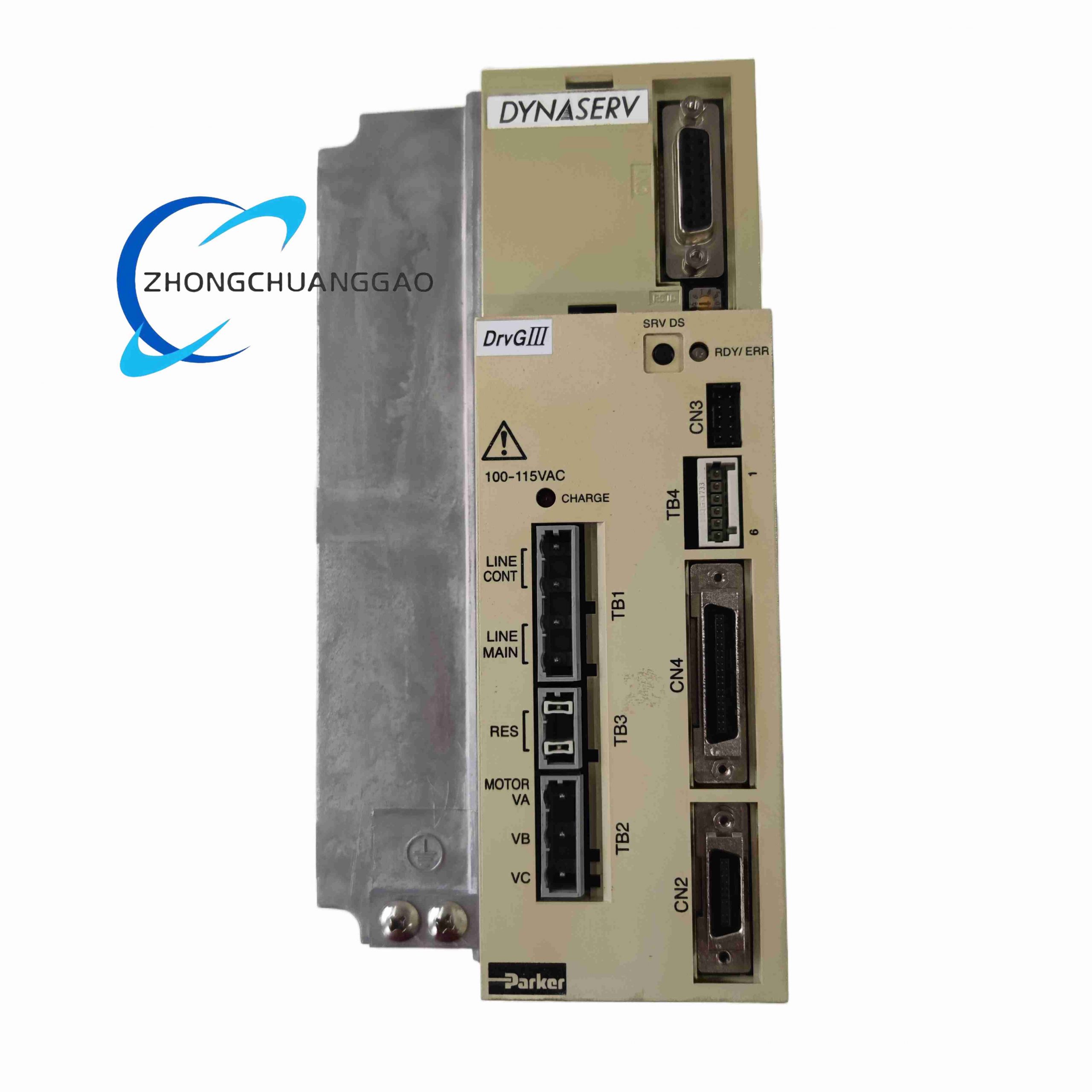
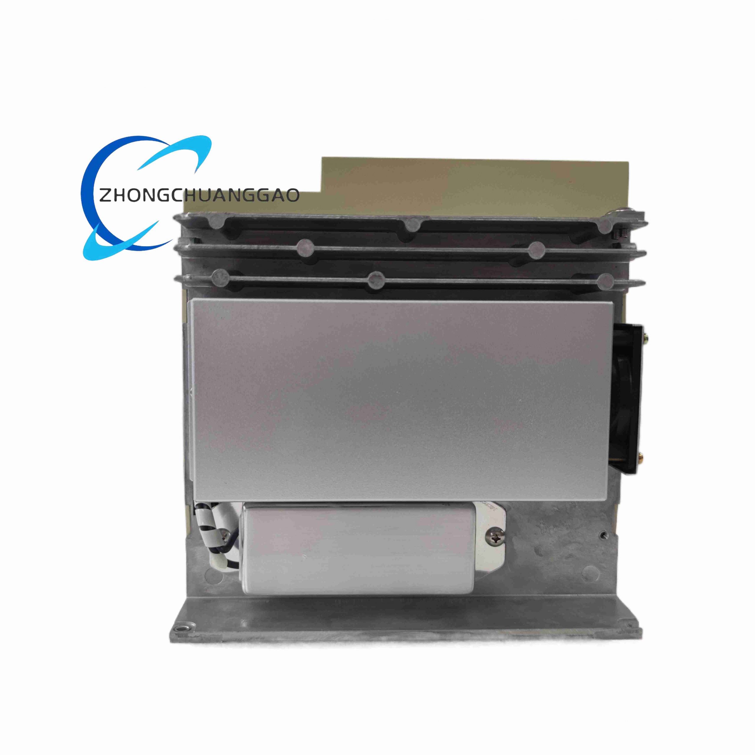
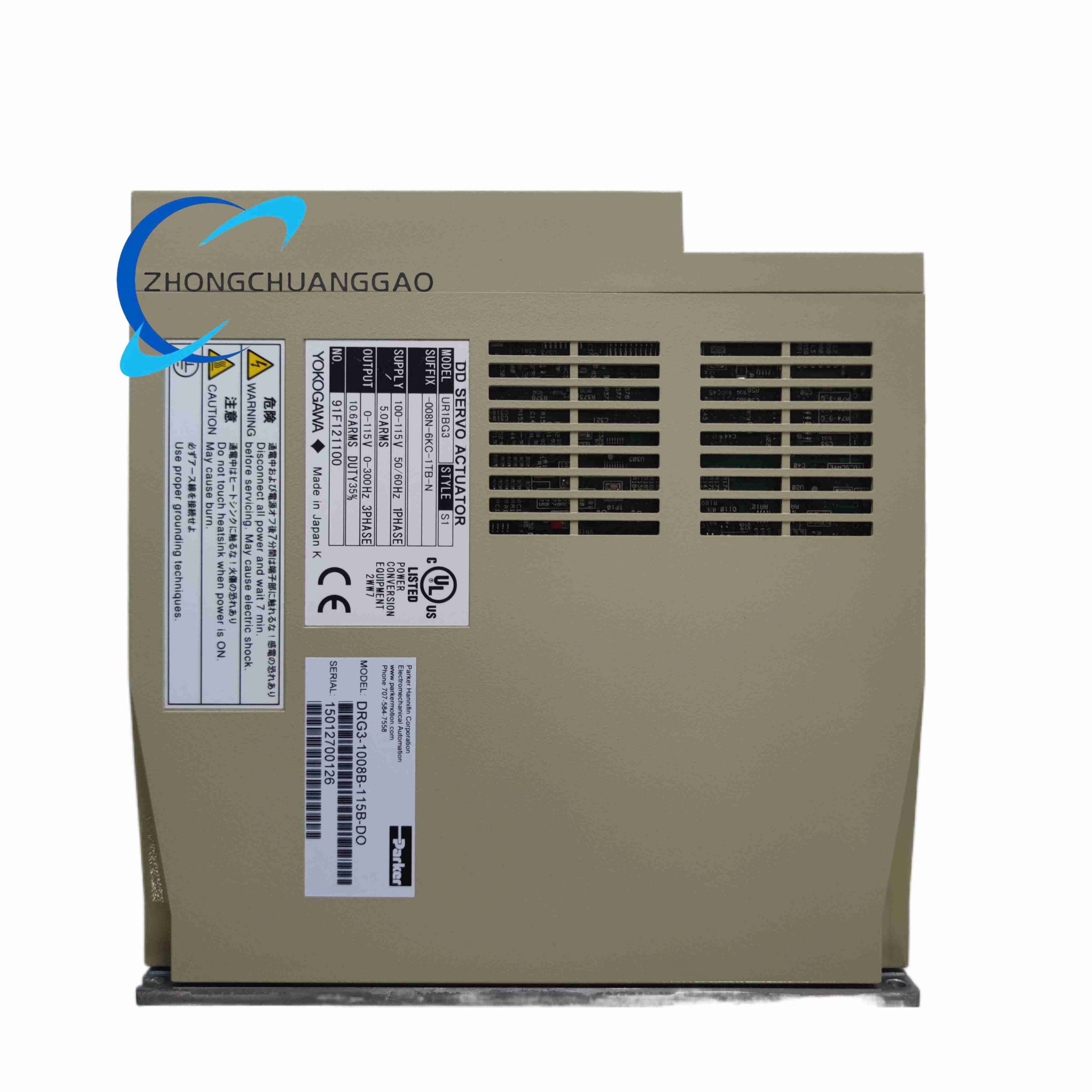
Description
Material Composition
- Outer housing: Black cold-rolled steel sheet with anti-oil splash epoxy coating
- Main power PCB: Thick copper industrial high-current printed circuit board
- Communication module substrate: Low-noise FR4 PCB with CAN bus isolated transceivers
- Power switching components: High-temperature low-loss IGBT power tubes
- Signal isolation hardware: Linear optocouplers + pulse transformer dual isolation for CAN bus
- Built-in heat dissipation: Extruded aluminum alloy fin heat sink bonded to power circuit area
- Terminal assembly: Nickel-plated copper spring clamping terminals, separate power, analog, valve output and CAN bus terminal zones
Structural Features
- EN 60715 standard 35 mm DIN rail compact rectangular body, identical outer dimension to DR1008B-230 for cabinet interchangeability
- Front panel multi-indicator LED array: power RUN, CAN bus communication status, per-channel drive working and fault alarm lights
- Independent partitioned terminal blocks: AC mains power input, analog signal input, hydraulic valve drive output, CANopen bus communication
- Dual isolation structure: analog signal isolation between control and power stage, galvanic isolation between CAN bus and internal drive logic
- Embedded temperature sensing probe attached to aluminum heat sink for real-time overheat monitoring
- Built-in non-volatile Flash memory for permanent storage of bus node address, channel gain, zero offset and protection threshold parameters
Technical Specifications
- Model Code: DRG3-1008B-230B
- Input Power Supply: 230 VAC single-phase, 50 / 60 Hz industrial mains
- Drive Channel Quantity: 8 fully independent proportional valve output channels
- Single Channel Continuous Drive Current Range: 0 ~ 2 A adjustable PWM output
- PWM Drive Fixed Switching Frequency: 1.2 kHz
- Dual Control Input Modes:
- Analog mode: 0–10 VDC voltage / 4–20 mA current signal
- Digital bus mode: CANopen DS408 hydraulic device standard protocol
- CANopen Bus Electrical Isolation Withstand Voltage: 2500 VAC dielectric strength
- Analog Signal Isolation Voltage: 1000 VAC between control and power drive circuit
- CAN Bus Baud Rate Range: 125 kbps, 250 kbps, 500 kbps, 1 Mbps software configurable
- Maximum Full-Load Power Consumption: 128 VA
- Operating Ambient Temperature Range: 0 ℃ ~ +55 ℃
- Storage Temperature Range: -25 ℃ ~ +70 ℃
- Unit Outer Dimension: 160 mm (L) × 110 mm (W) × 45 mm (D)
- Net Weight: 0.81 kg
- Compliance Standards: CE EMC, CANopen DS408 hydraulic device profile, IEC 61000-6-2 industrial immunity standard
Function Features
- Dual-mode operation support: pure analog signal control or full digital CANopen bus network control, switchable via software without hardware modification
- CANopen DS408 standard protocol compatibility, realizes remote online adjustment of each channel gain, zero offset, current limit and protection parameters
- Real-time data upload via CAN bus: channel output current, valve command value, heat sink temperature, fault state codes to upper-level PLC
- 8 isolated drive channels with independent closed-loop current feedback, zero cross-talk interference under simultaneous multi-valve operation
- Complete multi-level hardware protection: output short-circuit, coil open circuit, channel overcurrent, power overvoltage, internal overheat
- Front panel dedicated CAN communication LED indicator for fast on-site bus fault troubleshooting
- All configuration parameters stored in on-board Flash memory, retained permanently after mains power cut-off
- Compatible direct mechanical replacement with DR1008B-230; same DIN rail installation size and analog terminal layout
- Supports CAN bus node address automatic scanning and online firmware upgrade via industrial bus without dismounting unit from cabinet
- Built-in bus fault detection function: bus cable break, terminal resistance missing, node address conflict trigger coded alarm signal upload
Working Principle
230 VAC alternating current is rectified and filtered into stable DC bus voltage to supply power drive and CAN communication circuits. The unit accepts two types of control instructions simultaneously: analog voltage/current signals isolated via linear optocouplers, and digital command frames transmitted from CANopen bus through isolated pulse transformers. Internal main logic chip prioritizes bus commands when bus communication is active; analog signals serve as backup control source upon bus disconnection. Each of the 8 drive channels uses closed-loop current sampling feedback to stabilize PWM output current to proportional valve coils. CAN transceiver module performs bidirectional conversion between internal logic signals and differential bus signals, packaging channel working data and fault codes into standard DS408 protocol frames for transmission to the master PLC. The aluminum fin heat sink dissipates heat generated by high-current IGBT switching tubes, and the attached temperature probe triggers hardware shutdown when temperature exceeds safety threshold. Dual-layer galvanic isolation blocks ground loop and electromagnetic noise from factory power and long-distance bus cables.
Advantage Highlights
- Interchangeable with DR1008B-230, supports cabinet hardware upgrade without redesigning installation layout
- Native CANopen hydraulic standard bus eliminates separate communication gateway hardware cost for networked hydraulic systems
- Remote parameter modification and fault data upload reduce on-site manual calibration and maintenance downtime
- Dual analog/digital control mode ensures equipment continuous operation even if fieldbus network fails
- Higher CAN bus isolation withstand voltage adapts to long-distance bus wiring in high-interference heavy industry workshops
- Unified bus fault coding system simplifies upper-level HMI centralized alarm display for hydraulic equipment failure diagnosis
- Non-volatile parameter storage avoids repeated calibration after equipment power cycle
Applicable Industries
Automotive assembly hydraulic test benches, automated metal forging lines, multi-axis injection molding machinery, large port hydraulic cranes, wind turbine pitch hydraulic actuation systems, automated die-casting equipment, industrial robot hydraulic servo units
Installation Requirements
- Mount on standard EN 60715 35 mm DIN rail inside IP54 or higher grade electrical control cabinet
- Maintain minimum 30 mm vertical ventilation clearance above and below unit for passive heat dissipation
- CANopen bus wiring uses shielded twisted-pair CAN dedicated cable, install 120 Ω terminal resistance at two physical ends of bus trunk
- 230 VAC power cable cross-section ≥1.5 mm² copper wire, terminal tightening torque controlled at 0.8 N·m
- Analog signal wiring shield single-point grounded inside cabinet; CAN bus shielding grounded at master PLC cabinet only
- Maximum CAN bus cable total length limited by baud rate: 1 Mbps ≤ 40 m, 500 kbps ≤ 100 m, 250 kbps ≤ 250 m, 125 kbps ≤ 500 m
Usage Precautions
- Forbid removing CAN bus 120 Ω terminal resistance at bus trunk endpoints; missing resistance causes signal reflection and complete communication loss
- Do not perform CAN bus firmware upgrade during equipment full-load production; mains power interruption permanently damages internal Flash program
- Avoid installing unit adjacent to high-power frequency converters; strong electromagnetic radiation distorts CAN bus differential signals
- Clean aluminum heat sink fins every 6 months in metalworking environments to prevent dust-induced overheat shutdown
- All bus node addresses must be unique within one CAN network; address conflict triggers continuous communication fault alarms
- Disconnect AC mains power before modifying terminal wiring for analog, valve output or CAN bus circuits
Reviews
There are no reviews yet.