
Product Short Description
Product Overview
Description
Technical Core Specifications
- Main Central Processor: Motorola MC68040 CPU, clock frequency 25MHz, integrated floating-point arithmetic unit FPU, separate instruction and data cache.
- Onboard Memory Configuration:
Standard DRAM: 16MB high-speed parity-check industrial dynamic memory
Boot Flash ROM: 2MB non-volatile flash memory for firmware, bootloader and OS kernel storage
NVRAM: 128KB battery-backed non-volatile memory for parameter, calibration and runtime data storage
- Bus Standard: Full VMEbus A16/A24/A32 address space, D08/D16/D32 data transfer mode, master/slave dual bus operation mode.
- Integrated Communication Interfaces:
1 × AUI/10BASE-T Ethernet controller for TCP/IP network data transmission
2 × RS232/RS422 configurable serial communication ports (console port + auxiliary data port)
1 × VMEbus system timer and interrupt controller, supports 7 levels of VME hardware interrupts
- Auxiliary Onboard I/O: 8-channel digital input / 8-channel digital output TTL level auxiliary discrete I/O for local signal interlock
- Physical Form Factor: Standard 6U VME single-width board, 233.35mm × 160mm board dimension, single-slot VME rack installation.
- Power Supply Requirement: +5V main logic power, ±12V analog/serial interface auxiliary power, supplied by VME rack backplane power rail.
- Operating Ambient Temperature: -20°C ~ +70°C industrial standard; -40°C ~ +85°C rugged extended temperature variant.
- Relative Humidity Range: 5%RH ~ 95%RH non-condensing.
- Vibration & Shock Standard: Compliant with MIL-STD-810 military anti-vibration and anti-shock specification.
- Protection Class: IP20, only for installation inside sealed industrial VME chassis cabinets.
Functional Features
- Integrated MC68040 FPU floating-point unit supports high-precision real-time mathematical operation, suitable for motion trajectory calculation, sensor signal filtering and process closed-loop control algorithm operation.
- Dual independent serial ports support simultaneous local console debugging and external serial instrument data collection, configurable RS232/RS422 electrical levels for long-distance wired transmission.
- Onboard 10M Ethernet interface realizes remote program download, real-time data upload and network interconnection between multiple VME rack control systems via TCP/IP protocol stack.
- Battery-backed NVRAM retains calibration parameters, operating setpoints and fault log data after complete rack power failure, no repeated calibration required after power recovery.
- Master/Slave dual VME bus function: can act as main control master board to access all peripheral VME I/O modules, or work as slave data acquisition board responding to upper-level VME host commands.
- Built-in multi-level hardware interrupt controller achieves fast hardware event response, millisecond-level real-time control loop execution without software delay.
- Onboard 8DI/8DO local discrete I/O provides simple equipment interlock and status signal collection without extra auxiliary VME digital I/O boards.
- Firmware bootloader stored in flash ROM supports automatic OS startup, remote firmware update and fault self-diagnosis during power-on self-test (POST).
- Complete power-on self-test program automatically detects CPU, memory, Ethernet, serial ports and VME bus circuit faults, outputs fault code via console serial port for maintenance diagnosis.
- Wide industrial temperature tolerance and military-grade anti-vibration structure adapt to harsh outdoor, vehicle-mounted and mobile industrial control environments.
Material & Structural Composition
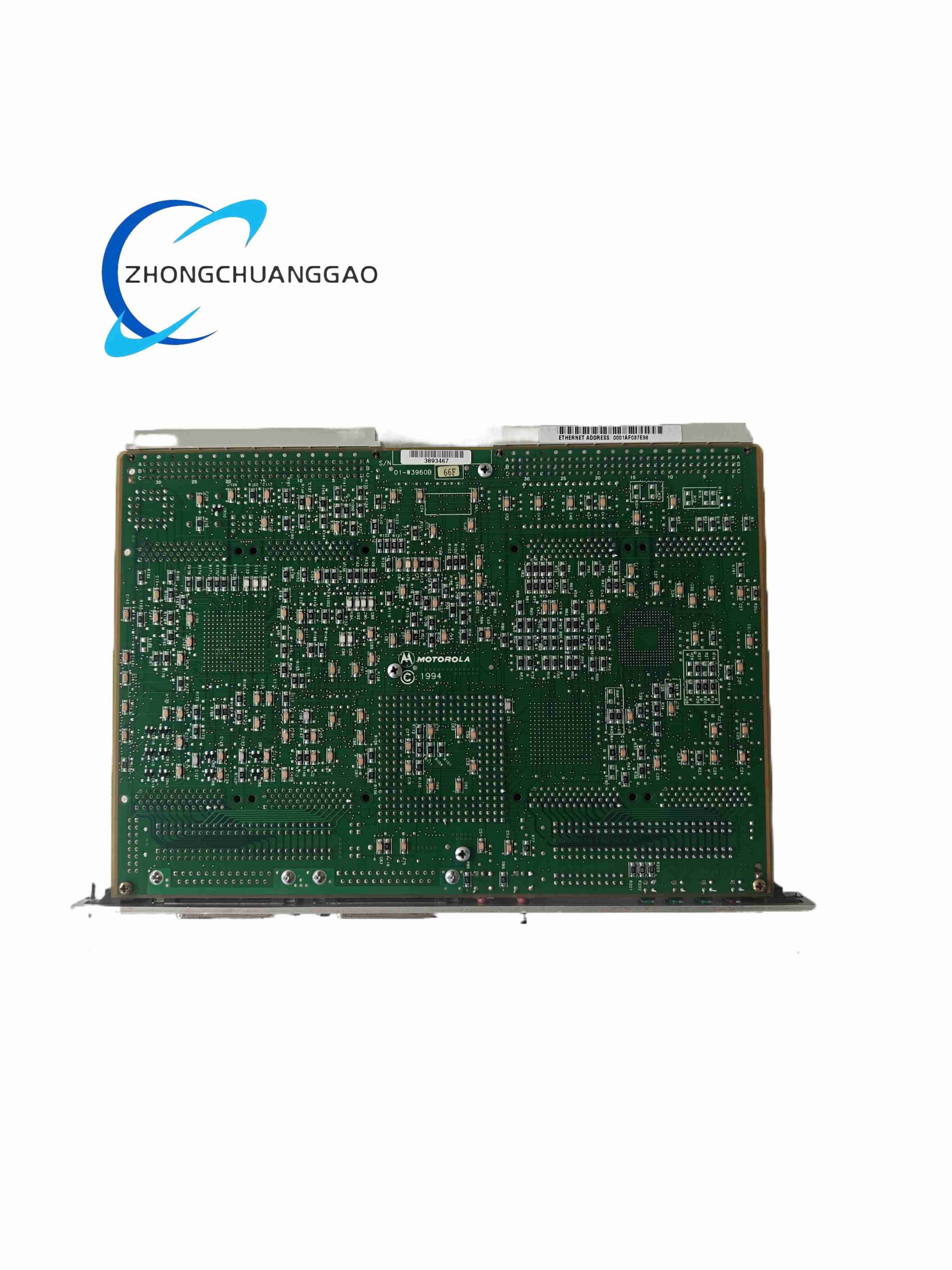
- Board Substrate: Thick multilayer FR4 military-grade printed circuit board, high thermal conductivity, full conformal polyurethane anti-corrosion, anti-moisture, anti-salt spray coating.
- Core Electronic Components: Industrial-grade wide-temperature CPU, DRAM and flash memory chips, tantalum low-leakage stable capacitors, high-reliability military specification resistors.
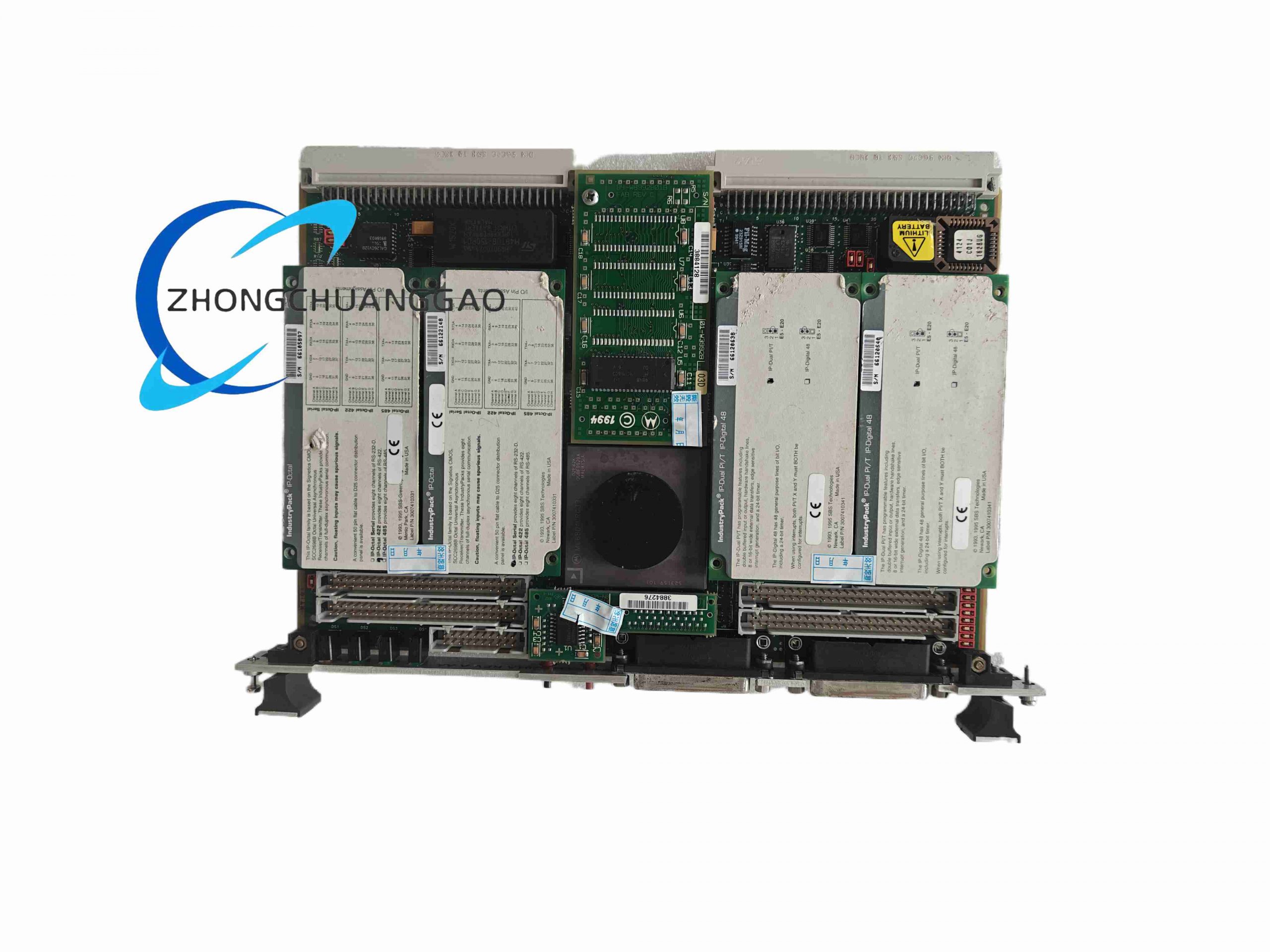
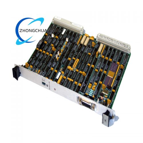
- Front Panel: Thick aluminum alloy CNC machined front panel with black oxidation anti-corrosion surface, equipped with Ethernet AUI/ RJ45 socket, dual serial DB9 connectors, power status LED and fault alarm LED indicators.
- VME Backplane Connector: High-density gold-plated multi-row pin VME standard connector, low contact resistance, resistant to long-term plugging and vibration oxidation.
- Backup Battery Module: Replaceable lithium coin cell battery compartment on PCB, independent isolated circuit to prevent battery leakage corrosion to main circuit.
- Heat Dissipation Structure: Embedded aluminum passive heat sink bonded to CPU and Ethernet controller chips to eliminate overheating under full-load continuous operation.
- Mechanical Reinforcement: Stainless steel locking brackets on both sides of the board for fixing inside VME rack, anti-vibration silicone gaskets to buffer mechanical impact.
Working Principle
The MC68040 CPU serves as the core computing unit: it reads sensor data from VME analog/digital I/O modules through VME bus master mode, executes user-compiled motion control, process regulation and interlock logic algorithms, and outputs control commands back to peripheral VME drive modules.
Dual serial ports exchange data with external serial instruments, debugging terminals and serial printers; the onboard Ethernet controller transmits real-time production data, fault logs and operating parameters to remote upper monitoring host via TCP/IP network.
All critical calibration values and fault history records are automatically written to battery-powered NVRAM. When rack power is cut off, the lithium battery continuously supplies power to NVRAM to prevent data loss.
The hardware interrupt controller captures fast external trigger signals from VME peripheral modules, suspends low-priority tasks immediately and responds to high-priority control events to guarantee real-time performance of industrial control loops.
The auxiliary 8DI/8DO local I/O directly collects field switch status and outputs relay drive signals for simple local equipment interlock without occupying VME bus bandwidth.
Installation Requirements
- Install into standard 6U single-width slot of VME64 industrial rack, vertical chassis mounting is the preferred installation orientation.
- Install dedicated rack forced air cooling fans above the VME chassis; maintain minimum airflow rate of 15CFM for single board heat dissipation under full load.
- Reserve one empty slot between MVME162-513A and high-power analog output VME modules to avoid thermal stacking and electromagnetic interference.
- Separate Ethernet and serial communication wiring from high-current AC power cables with minimum 20cm distance inside the cabinet.
- Replace the onboard lithium backup battery every 5 years; complete power off the whole VME rack before battery replacement to avoid NVRAM data loss.
- All communication cables must use shielded twisted pair cable, single-point shielding grounding at cabinet earth bar, double-end grounding is forbidden.
- Fix VME board front panel locking screws tightly to eliminate vibration-induced loose connector contact during long-term operation.
Application Scenarios
Operation & Maintenance Notes
- Export OS mirror, application program and system parameter files to external storage medium after project commissioning for hardware replacement recovery backup.
- Check front panel power and fault LED status daily; analyze serial console POST fault codes immediately once abnormal alarm light is triggered.
- Conduct annual battery replacement to prevent lithium battery leakage, which will corrode PCB traces and cause permanent board failure.
- Do not operate the VME rack without cooling fans; sustained high temperature will lead to CPU memory chip aging and random system crash faults.
- Avoid opening the sealed industrial cabinet in dusty, corrosive vapor and salt spray environments without extra air filtration devices.
- Cut off the whole rack power supply completely before pulling out or inserting the MVME162-513A board to prevent backplane bus short-circuit and component burnout.
- If frequent data loss occurs after power failure, inspect NVRAM battery voltage and replace the backup battery immediately.
Reviews
There are no reviews yet.