
Product Short Description
Product Overview
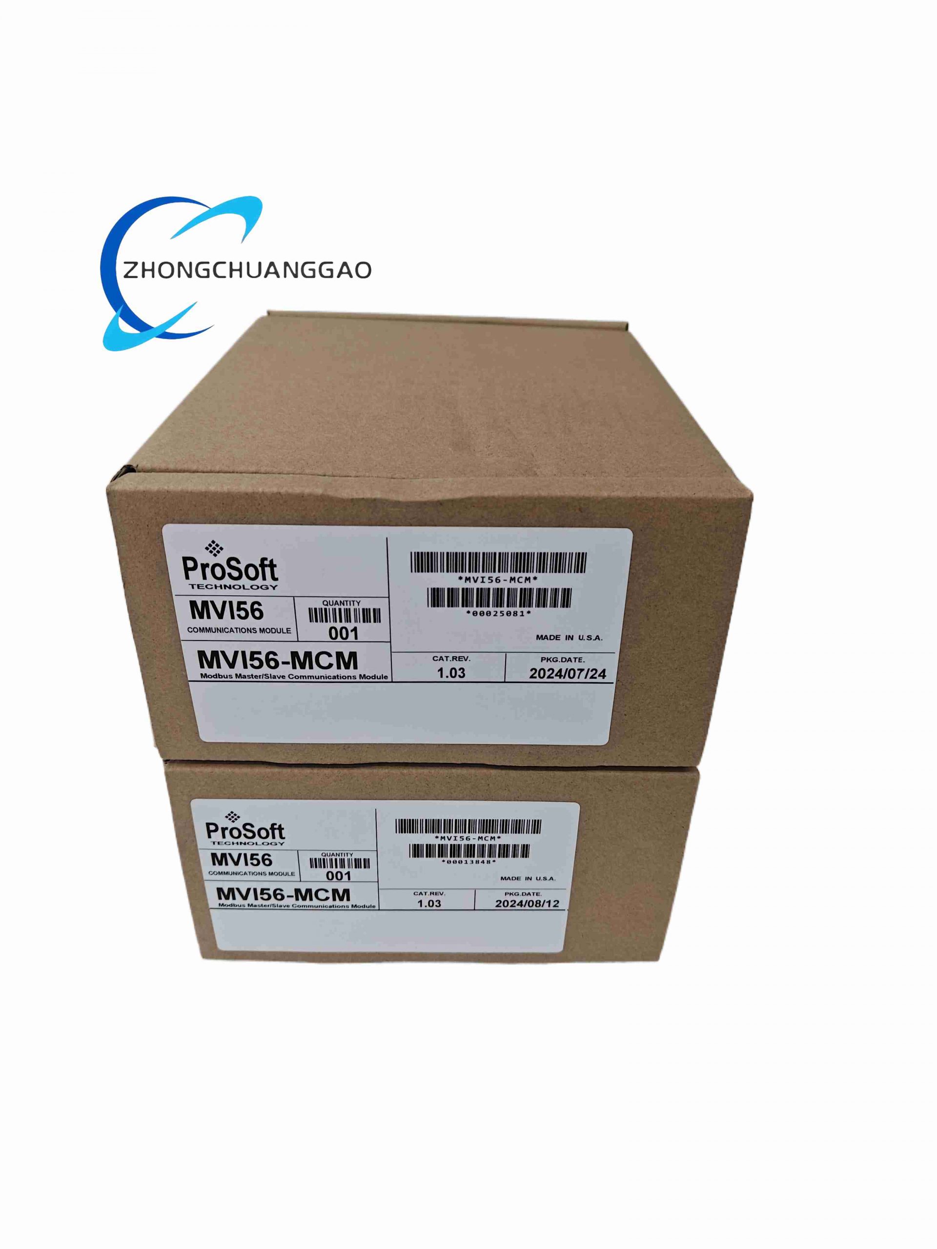
Description
Technical Core Specifications
- Compatible PLC Platform: Rockwell ControlLogix 1756-series backplane chassis (all L6x, L7x, L8x CPU models)
- Serial Communication Ports: Two fully isolated RS-485/RS-232 configurable ports
- Supported Modbus Protocols: Modbus RTU (CRC-16 error checking), Modbus ASCII (LRC error checking)
- Baud Rate Range: 110 baud to 115,200 baud user configurable per port
- Serial Format Options: Data bits (7/8), stop bits (1/2), parity (None / Even / Odd)
- Modbus Function Code Support: Complete standard Modbus read/write coil, discrete input, holding register, input register, diagnostic and mask write function codes
- Floating-Point Data Handling: Configurable byte/word swapping for Enron, Daniel and industry-standard 32-bit floating-point register mapping
- Backplane Data Exchange: Direct mapped I/O data blocks between module and ControlLogix CPU memory via chassis backplane high-speed DMA transfer
- Module Status Indication: Four-digit front-panel LED diagnostic display for real-time port communication fault and module configuration status
- Operating Temperature Range: -20°C ~ +60°C standard industrial cabinet operation
- Storage Temperature: -40°C ~ +85°C
- Physical Form Factor: Standard 1756 single-slot ControlLogix rack plug-in module
Functional Features
- Dual independent serial ports allow simultaneous Modbus master polling of field transmitters and Modbus slave response to external HMI/SCADA systems on separate wiring networks
- Configurable per-port Modbus master polling interval (0–65535ms) to optimize network bandwidth allocation for high/low priority field device data
- Onboard protocol processing CPU offloads all Modbus communication parsing workload from the main ControlLogix PLC processor, reducing CPU scan cycle load
- User-defined Modbus register-to-Controller tag mapping eliminates complex ladder logic data conversion routines
- Comprehensive diagnostic fault logging records port timeout errors, slave device no-response events, parity and CRC communication check failures
- ProSoft Configuration Builder (PCB) Windows-based configuration software provides graphical interface for serial port parameters, Modbus register mapping, master polling schedules and fault alarm thresholds, supports offline project save and USB download/upload to module.
- Full electrical galvanic isolation between two serial communication ports and ControlLogix backplane circuit, eliminates ground loop noise damage between Modbus field equipment and PLC rack.
- Built-in serial surge protection components suppress voltage transients induced by long field wiring, reduces communication breakdown caused by lightning and contactor switching interference.
- Supports multi-drop Modbus bus topology, single RS485 port can connect maximum 32 Modbus slave devices without external signal repeaters.
- Automatic fault skip function: unresponsive offline slave addresses are temporarily excluded from polling queue to avoid overall Modbus network response delay.
Material & Structural Composition
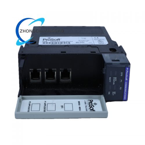
- Front Panel: Black matte flame-retardant ABS plastic, embedded 4-digit seven-segment LED diagnostic screen, multi-color status LEDs for backplane link, Port 1 communication, Port 2 communication and module fault alarm.
- Main PCB: Multi-layer FR4 industrial circuit board with full conformal acrylic anti-moisture, anti-dust coating; independent isolated power circuits for backplane and two serial ports.
- Serial Interface Circuits: High-speed RS485 transceivers with built-in TVS surge suppression diodes and isolation transformers.
- Backplane Connector: Gold-plated multi-pin edge connector compatible with 1756 ControlLogix rack backplane, low contact resistance for long-term continuous operation.
- Internal Core Hardware: Independent 32-bit dedicated communication microcontroller, on-board flash memory for storing user Modbus mapping configuration, SRAM for real-time communication buffer data.
- Structural Frame: Reinforced glass-filled nylon rack lock bracket with anti-vibration rubber gaskets to reduce mechanical vibration impact during factory production runtime.
Working Principle
The MVI56-MCM module inserts into a single empty slot of Rockwell ControlLogix rack and establishes high-speed DMA data exchange with the PLC CPU via the backplane bus. The onboard independent microcontroller handles all Modbus protocol parsing tasks separately without occupying main PLC scan cycle resources.Users configure communication mode (master/slave), baud rate, parity, polling sequence and register mapping rules through PCB software, then download configuration files to module flash memory.
When operating as Modbus Master, the module actively sends read/write request frames to all connected RTU/ASCII slave instruments, sensors, drives and meters via RS232/RS485 serial ports; received response data is converted into uniform integer/float data blocks and synchronized to PLC controller tags through backplane real-time data buffer.
When operating as Modbus Slave, the module listens to external Modbus master request signals on serial ports, extracts target register addresses from request frames, reads corresponding data from ControlLogix memory and returns standard Modbus response frames.
Galvanic isolation transformers separate field serial circuit and PLC internal circuit to block ground loop current, while built-in fault logic records communication timeouts, CRC errors and offline slave information into onboard diagnostic logs for maintenance inspection.
Installation Requirements
- Install only inside IP54 rated industrial electrical cabinets, standard vertical ControlLogix rack mounting; horizontal rack installation is allowed but needs extra cabinet cooling fans.
- Reserve minimum 10mm horizontal clearance between MVI56-MCM and adjacent PLC power supply or high-power analog modules to avoid thermal accumulation.
- For RS485 multi-drop Modbus wiring, use shielded twisted pair industrial communication cable; cable total length cannot exceed 1200 meters at 9600 baud rate.
- Termination resistor jumper must be enabled only at the two farthest end devices of the Modbus trunk line to eliminate signal reflection distortion.
- All shield cable shielding layers must be single-point grounded at the cabinet earth bar; double-end grounding is strictly prohibited.
- Torque serial port terminal block screws to 2.8 Nm; stranded wires must be fitted with wire ferrules before wiring to prevent loose contacts.
- Keep Modbus communication wiring separated from 380V/220V high-power motor cables with minimum 15cm physical distance to avoid electromagnetic interference.
Application Scenarios
Factory assembly line Modbus sensor data collection, water treatment plant flow/pH/level Modbus transmitter connection, oil & gas pumping station Modbus flow meter integration, food processing production line frequency converter Modbus communication, building energy monitoring Modbus power meter data acquisition, mining underground Modbus pressure sensor monitoring, cement plant kiln auxiliary equipment Modbus data interconnection, municipal sewage PLC control system Modbus instrument expansion.Operation & Maintenance Notes
- Download backup configuration project files to local PC after completing parameter setup for rapid replacement recovery when module hardware fails.
- Check the 4-digit front LED diagnostic code weekly to locate port communication faults, slave offline errors and mapping configuration mismatches timely.
- Do not connect RS232/RS485 serial ports to high-voltage circuits; transient overvoltage will permanently damage internal isolation transceivers.
- Clean cabinet cooling fans and filter screens monthly; high temperature environment will shorten the service life of onboard communication chips.
- Replace the module if persistent CRC communication errors still exist after checking wiring, shielding and terminal tightness.
- Avoid frequent hot swapping of the module during PLC running state; power off the rack before disassembly to prevent backplane circuit short-circuit damage.
-500x500.jpg)
Reviews
There are no reviews yet.