
Product Short Description
Product Brief Introduction
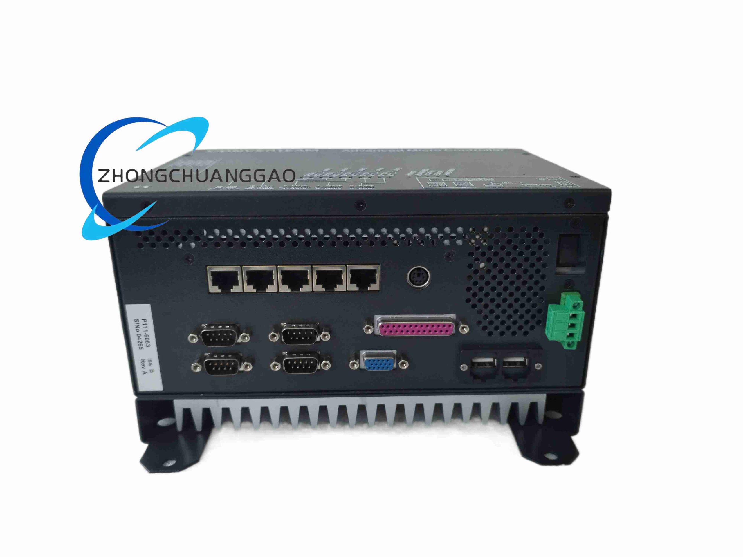
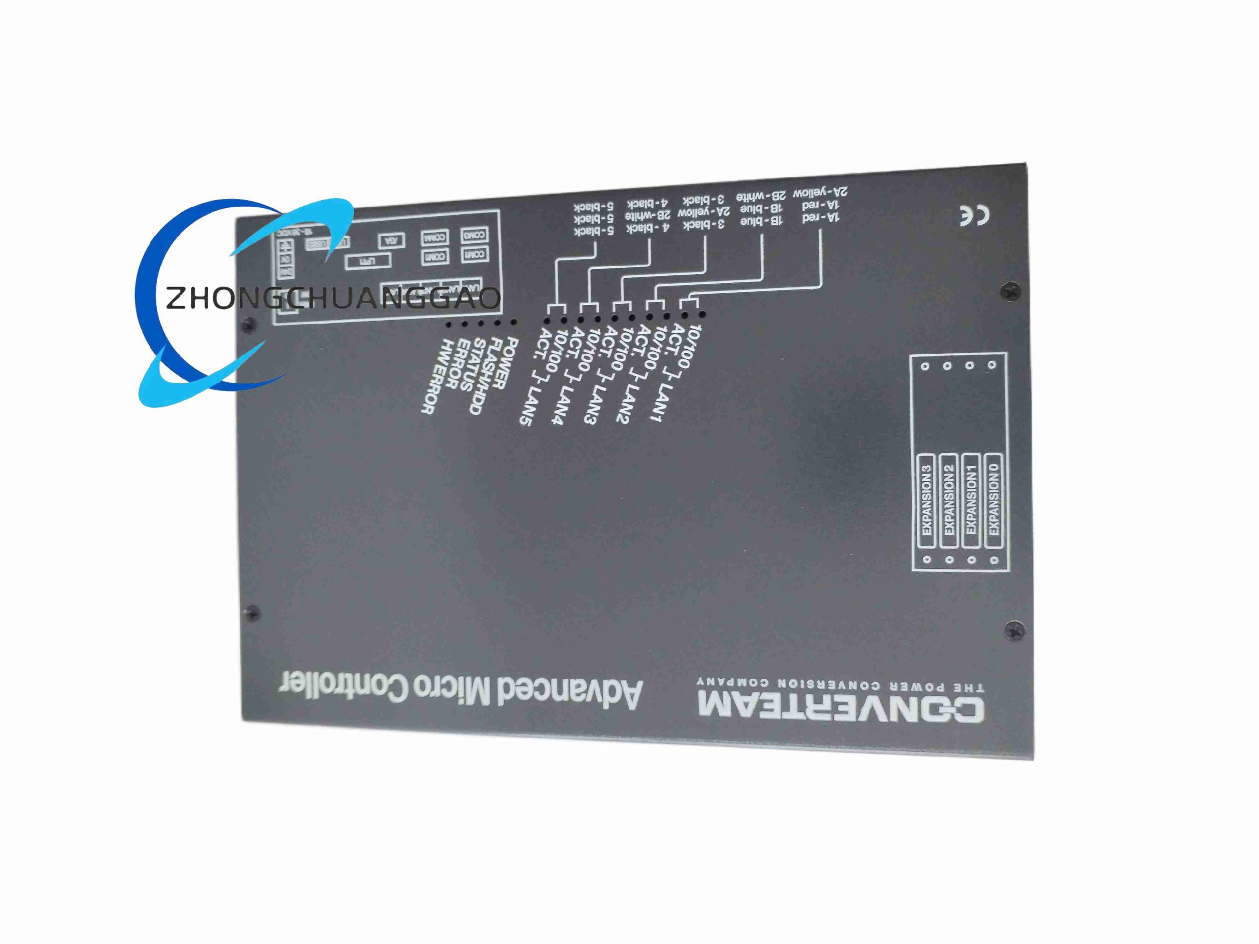
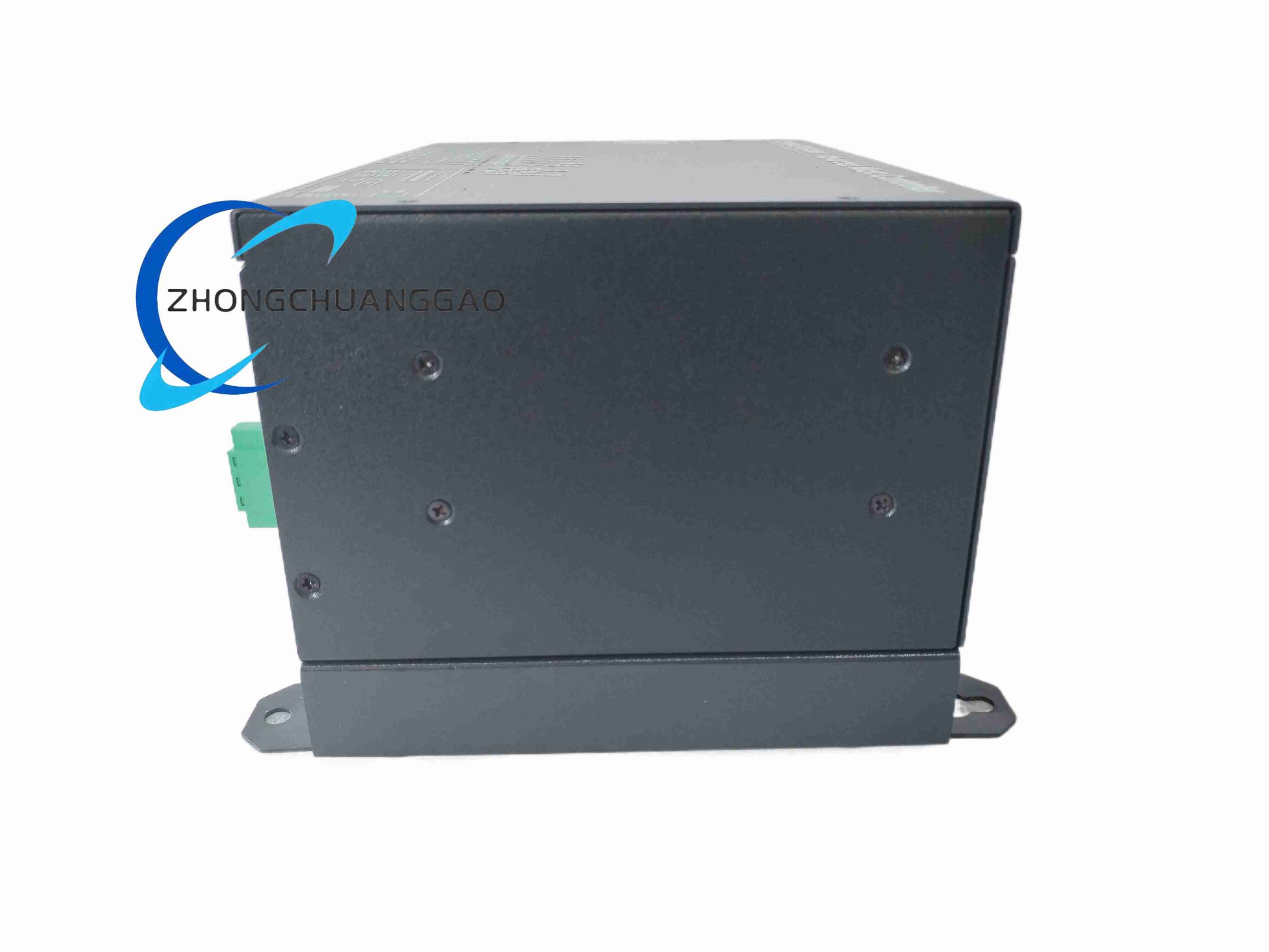
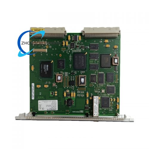
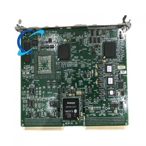
P111-6053 is a dedicated signal conditioning printed circuit board manufactured by General Electric for industrial power plant, turbine and heavy equipment monitoring systems. It converts weak field sensor signals (thermocouple, RTD, 4–20mA transducers) into standardized isolated analog voltage signals compatible with GE series PLC and data acquisition racks, providing surge protection, noise filtering and galvanic isolation for high-interference power industry environments.
Description
Core Technical & Performance Parameters
- Supported Input Signal Types: PT100 RTD, K/T/J/S thermocouple, 0–5V voltage, 4–20mA current loop
- Channel Quantity: 8 independent isolated signal input channels on single board
- Galvanic Isolation Rating: 2500VAC channel-to-backplane isolation, eliminates ground loop interference
- Signal Conversion Precision: Total measurement error ≤ ±0.15% full scale, 16-bit analog-to-digital conversion matching
- Built-in Filter: 4-order low-pass analog filter, cutoff frequency 10Hz to suppress industrial power frequency 50/60Hz noise
- Surge Protection: Bi-directional TVS diode and gas discharge tube integrated on each input channel, withstands 2kV ESD surge
- Backplane Bus Interface: GE proprietary 16-bit parallel industrial rack bus, maximum data refresh rate 2ms per full board
- Power Consumption: Maximum 4.8W, powered by rack backplane +5VDC and ±12VDC auxiliary power
- Operating Temperature: -10°C ~ +65°C; storage temperature -40°C ~ +85°C
- Humidity Range: 5%–90% RH non-condensing
- Mechanical Dimension: Standard 4U rack plug-in board, 160mm height × 220mm depth × 30mm width
- MTBF: 245,000 hours under power plant industrial environmental conditions
Function & Feature Highlights
- Eight fully independent isolated channels, each channel with separate signal conditioning circuit, single channel fault will not affect other measurement loops
- Multi-type universal signal input, configurable via on-board DIP switch without hardware replacement for different sensor types
- High-strength surge and lightning protection circuit designed for power plant substation heavy electromagnetic interference environment
- Built-in cold junction compensation circuit for thermocouple inputs, automatically compensates terminal block ambient temperature error
- Hardware over-range signal locking protection; prevents overvoltage input from damaging rear-end acquisition CPU modules
- On-board diagnostic LED indicators for each channel, display open circuit, short circuit and over-range sensor fault status
- Backplane hot-plug compatible design; single board can be replaced without full rack power shutdown
- Conformal coated PCB standard configuration, resists sulfur vapor, dust and high humidity in thermal power plant control rooms
Material & Structural Characteristics
- Main PCB: 10-layer high-temperature FR4 industrial circuit board, controlled impedance signal routing for low noise analog signals
- Surface Coating: Transparent acrylic conformal coating covering all circuit traces, resist mild corrosive gas and moisture
- Front Panel: Black anodized thin aluminum panel with silk-screened channel labels and red/green fault status LEDs
- Connectors: Gold-plated spring terminal signal input connectors, high-density gold-plated edge connector for rack backplane communication
- Isolation Components: High withstand voltage isolation transformers installed per channel, separate analog and digital ground planes on PCB
- Mechanical Locking: Two front panel locking screws with spring anti-loose washers to resist vibration loosening in turbine rack cabinets
- Heat Dissipation: Passive copper thermal vias distributed across PCB to evenly spread heat generated by isolation transformers
Working Principle
- Field sensor weak analog signal enters independent channel circuit through front terminal block
- Surge protection components absorb instantaneous high voltage interference from power grid lightning or motor switching
- Low-pass analog filter eliminates high-frequency electromagnetic noise mixed in sensor signal
- Isolation transformer separates field side and rack control side circuits to cut off ground loop current
- Cold junction compensation circuit calibrates thermocouple temperature offset caused by terminal block temperature change
- Conditioned standard analog signal transmits to backplane bus, sent to upper GE CPU data acquisition module for calculation and storage
- Channel fault detection circuit continuously monitors input impedance; open/short circuit triggers front panel LED alarm and uploads fault code via backplane bus
Installation Requirements
- Insert vertically into standard GE series 4U industrial rack backplane slot, lock front panel screws with torque 0.6–0.9 N·m
- Maintain minimum 8mm vertical airflow gap between adjacent plug-in boards to avoid heat accumulation
- All sensor input wiring must use shielded twisted pair cables; shield grounding only at the rack cabinet earth bar end
- Thermocouple signals must use matched compensation wire; do not use ordinary copper wire for long-distance transmission
- Rack backplane power supply must have low ripple output (<30mV) to avoid analog measurement drift
- Cabinet must maintain ventilation to prevent condensation; condensation will cause conformal coating insulation performance degradation
Application Scenarios
- Thermal power plant boiler, turbine temperature and pressure signal collection racks
- Hydropower station generator unit vibration and temperature monitoring system
- Heavy industry steel mill furnace multi-point temperature data acquisition
- Nuclear power auxiliary equipment secondary monitoring signal conditioning cabinet
- Large compressor, gas turbine on-board sensor signal processing system
- Substation transformer winding temperature centralized monitoring system
Operation & Maintenance Notes
- Do not hot-swap the board when rack is powered on for long-term continuous operation; frequent hot plug reduces edge connector gold plating service life
- Adjust DIP switch sensor type configuration only after cutting off rack power supply to avoid signal circuit short-circuit damage
- Every 12 months inspect front terminal block for oxidation in high-humidity coastal power plants; clean terminals with isopropyl alcohol
- Avoid spraying liquid cleaning agent directly on PCB conformal coating surface; use dry compressed air to remove dust
- If multiple channels generate measurement drift simultaneously, check rack backplane ±12V auxiliary power supply ripple voltage
- When replacing the board, record DIP switch position settings of original board to ensure consistent sensor signal configuration after replacement
Reviews
There are no reviews yet.