
Product Short Description
Product Introduction
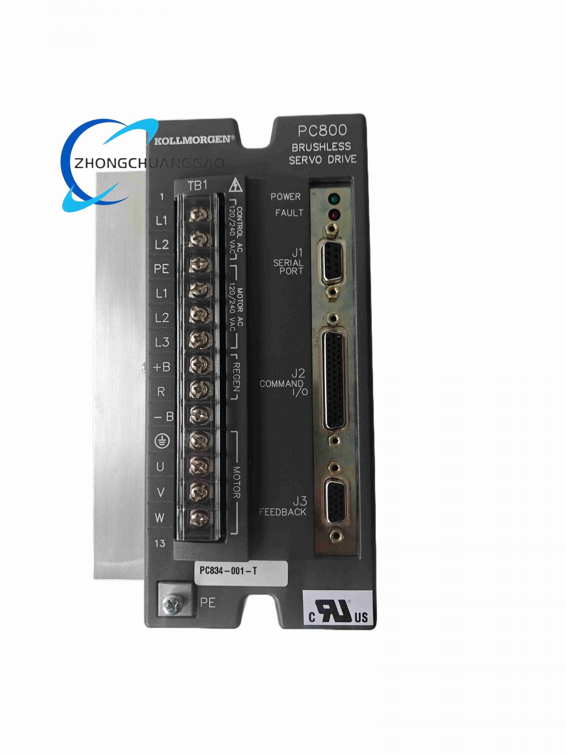
The Pacific Scientific PC834-001-T is a high-performance single-axis digital brushless servo drive belonging to the PC800 motion control product line (brand now integrated under Kollmorgen motion division). It delivers precision closed-loop torque, velocity, and position control for medium-power brushless permanent magnet servo motors, targeting industrial automation equipment requiring fast dynamic response and ultra-high positioning accuracy. The drive integrates advanced resolver-to-digital conversion (DRDC) algorithms and multi-mode command interfaces to support seamless connection with PLC motion controllers, CNC machine tools, and standalone positioning systems.
Description
Power & Current Ratings
- Continuous RMS Output Current (25°C ambient): 7.1 A
- Peak Transient RMS Output Current (0.5 s duty cycle): 21.2 A
- Input Power Supply Compatibility: 110/230 VAC single-phase mains supply
- Maximum Continuous Motor Torque Compatibility: 0.5 N·m to 48.5 N·m servo motor range
Motion Control Performance
- Position Feedback Resolution: 24-bit high-resolution resolver/encoder position conversion
- Servo Loop Bandwidth: 400 Hz high-speed closed-loop response bandwidth
- Supported Control Modes: Torque closed-loop, velocity closed-loop, position closed-loop indexing
- Command Input Interfaces: ±10 V analog velocity/torque command, Step/Direction pulse train, RS-232/RS-485 serial digital command, SERCOS industrial motion bus
- User Configurable Digital I/O: 6 mappable opto-isolated digital inputs, 3 mappable digital outputs, 1 fault relay output contact
Environmental & Physical Specifications
- Operating Ambient Temperature: 0°C to +40°C full rated current; +40°C to +55°C derated operation
- Storage Temperature Range: -30°C to +85°C
- Relative Humidity: 5%–90% non-condensing
- Protection Rating: IP20 cabinet mounting rating
- Mounting Standard: 35 mm DIN rail or flat panel screw mounting
- Module Dimensions: 240 mm height × 110 mm width × 65 mm depth
- Net Weight: 1.1 kg
Function Features
- Advanced DRDC resolver-to-digital conversion algorithm delivering noise-immune 24-bit position measurement without high-cost optical encoders
- Three independent closed-loop control modes (torque, speed, position) configurable via PC-based motion setup software
- Comprehensive integrated motor protection suite: overcurrent shutdown, overvoltage/undervoltage mains protection, drive over-temperature thermal cutback, motor stall detection, phase loss protection
- Six user-mappable digital inputs support limit switches, home position sensors, enable run signals, and mode selection logic
- SERCOS bus interface enables high-speed synchronized multi-axis motion coordination for CNC machining centers
- Onboard non-volatile memory stores up to 30 custom motion index profiles for standalone automated cycle execution
- Compact vertical DIN rail mount design minimizes cabinet footprint for multi-axis machine control panel layouts
Application Scenarios
- CNC vertical machining center single-axis spindle and linear slide servo control
- Automated semiconductor wafer handling precision positioning stages
- High-speed packaging machine labeling, cutting, and filling linear axis motion
- Robotics joint medium-power brushless servo motor drive control
- Printing press register correction high-response velocity regulation axes
Working Principle
AC mains input power enters internal active power factor correction circuits before feeding three-phase pulse-width-modulated (PWM) power inverter bridges driving the brushless servo motor stator windings. Resolver or incremental encoder position feedback signals connect to dedicated feedback interface ports; analog resolver signals undergo DRDC digital conversion to generate high-resolution absolute position data. The onboard 32-bit motion DSP executes PID closed-loop control algorithms using the position feedback signal and incoming motion command values (analog voltage, step pulses, or SERCOS bus digital commands). The DSP calculates required PWM output voltage waveforms to adjust motor torque and velocity, continuously correcting position error at 400 Hz loop bandwidth. All drive operating parameters, fault states, and motion profile data are accessible via RS-232/485 serial communication for configuration and real-time monitoring on host PC software.
Material Composition
- Main Power PCB: Heavy copper FR4 printed circuit board with high-current power trace layout, industrial conformal coating
- Power Switching Hardware: IGBT PWM inverter power modules, high-frequency bus electrolytic capacitors
- Control Logic PCB: Separate low-voltage signal daughterboard with motion DSP, resolver signal conditioning circuits
- Enclosure Housing: Black cold-rolled steel stamped casing with integrated vertical aluminum heat sink fins
- Terminal Connectors: Screw-clamp copper power terminals for motor mains wiring, D-sub connectors for feedback and serial communication ports
Structural Features
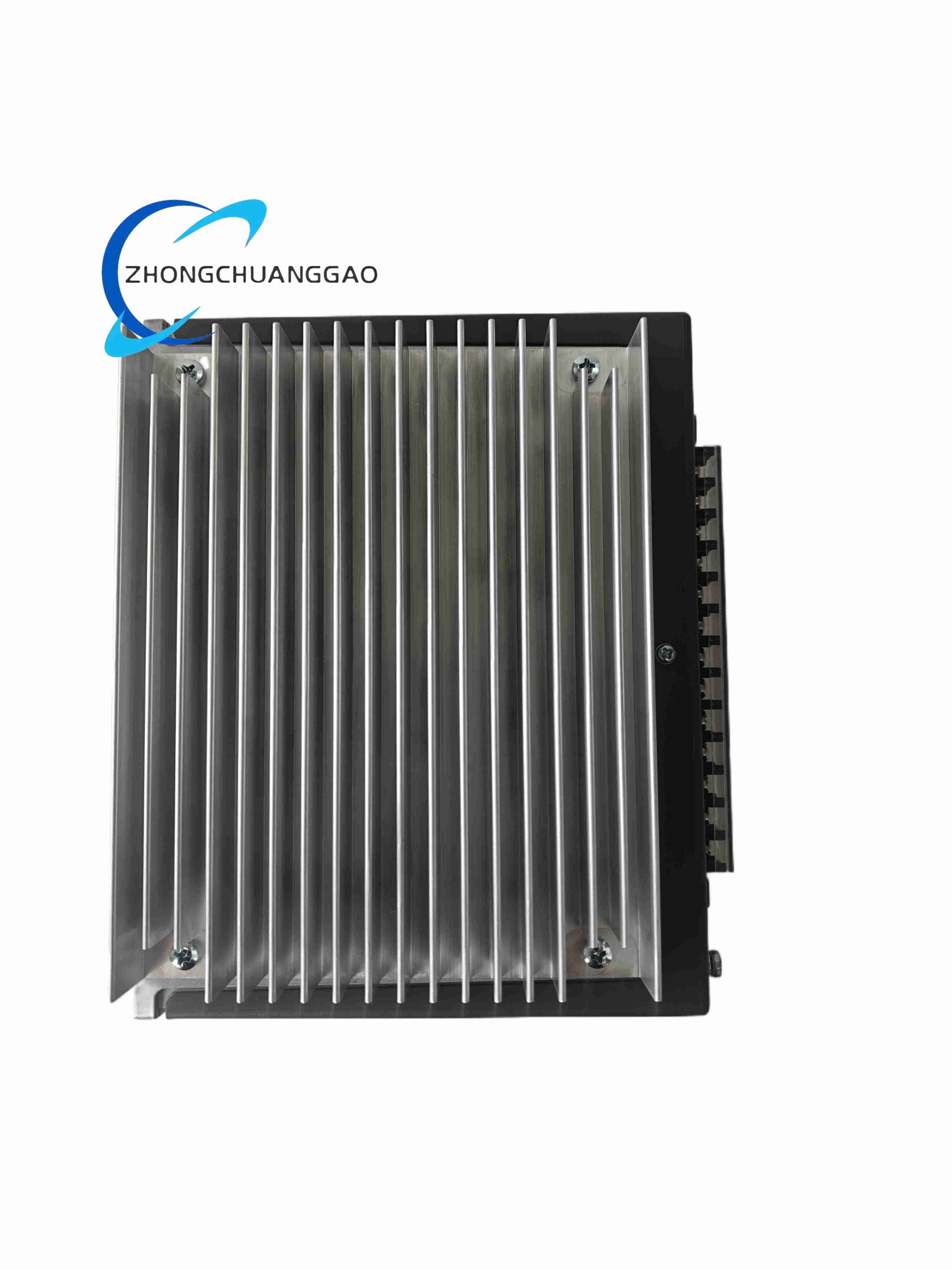
- Vertical aluminum fin heat sink spanning full rear panel for maximum passive thermal dissipation during peak current operation
- Front panel segmented terminal layout segregating mains power terminals, motor output terminals, digital I/O wiring, and communication D-sub ports
- Front panel LED status array indicating power supply active, drive fault alarm, motor enable state, and SERCOS bus communication activity
- Dual mounting design: integrated DIN rail clip plus four rear mounting holes for direct flat panel installation
- Removable transparent plastic terminal cover to prevent accidental contact with live high-current wiring terminals
Installation Requirements
- Mount drive vertically only; horizontal installation reduces heat sink airflow and requires 30% current derating
- Maintain minimum 30 mm vertical clearance above and below the unit for convection cooling airflow
- Install external mains surge protection upstream of the drive AC input terminals to suppress grid voltage transients
- Torque high-current motor and mains power terminal screws to 1.2–1.5 N·m to eliminate thermal hot spots under peak load
- Route resolver/encoder feedback cables as shielded twisted pair with single-point cabinet grounding; separate from high-current motor power wiring by minimum 15 cm
- Connect drive chassis protective earth terminal to cabinet main ground bus using minimum 2.5 mm² copper grounding wire
Usage Precautions
- Do not operate the drive above +40°C ambient temperature at full 7.1 A continuous current rating; derate output current linearly as temperature rises to +55°C
- Always disconnect AC mains supply before removing terminal wiring or opening the drive enclosure cover for maintenance
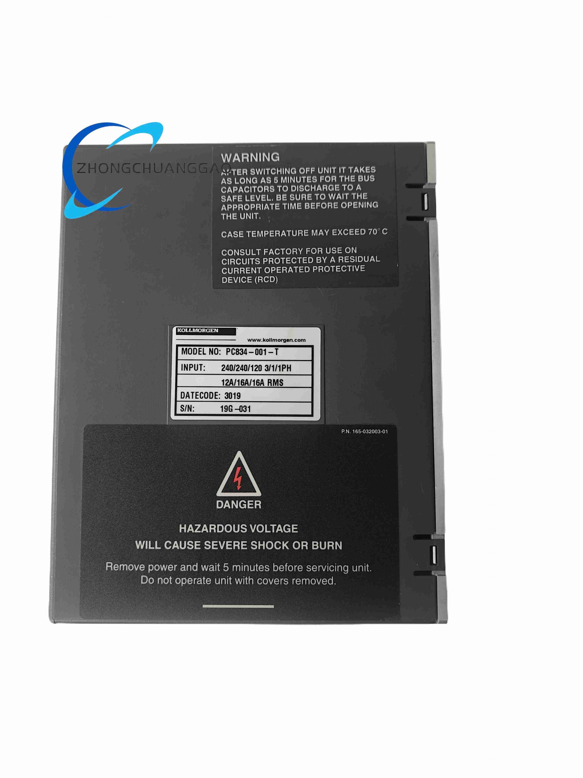
- Allow minimum 10-minute capacitor discharge period after power shutdown before touching internal power circuit components
- Use only Pacific Scientific compatible resolver/encoder feedback devices; mismatched feedback hardware causes severe positioning drift and drive fault shutdown
- Avoid deploying the drive in environments with conductive dust or oil mist without fully sealed IP54 rated control cabinets
- Calibrate resolver feedback offset values via setup software after every motor or drive replacement to maintain 24-bit position measurement accuracy
-500x500.jpg)
Reviews
There are no reviews yet.