
Product Short Description
Product Brief Introduction
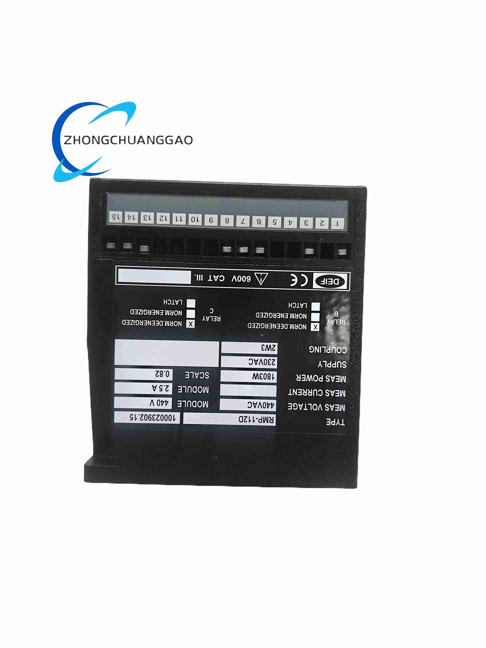
DIN rail mounted three-phase generator protective relay manufactured by DEIF Denmark, complies with ANSI Code 32 standard, integrated dual protection functions: generator overload protection and reverse power anti-motoring protection. Widely applied on marine vessel diesel generators and land-based backup gensets to prevent prime mover overload and generator reverse power motoring damage during parallel grid operation.
Description
Core Technical Performance Parameters
Measurement & Protection Threshold Range
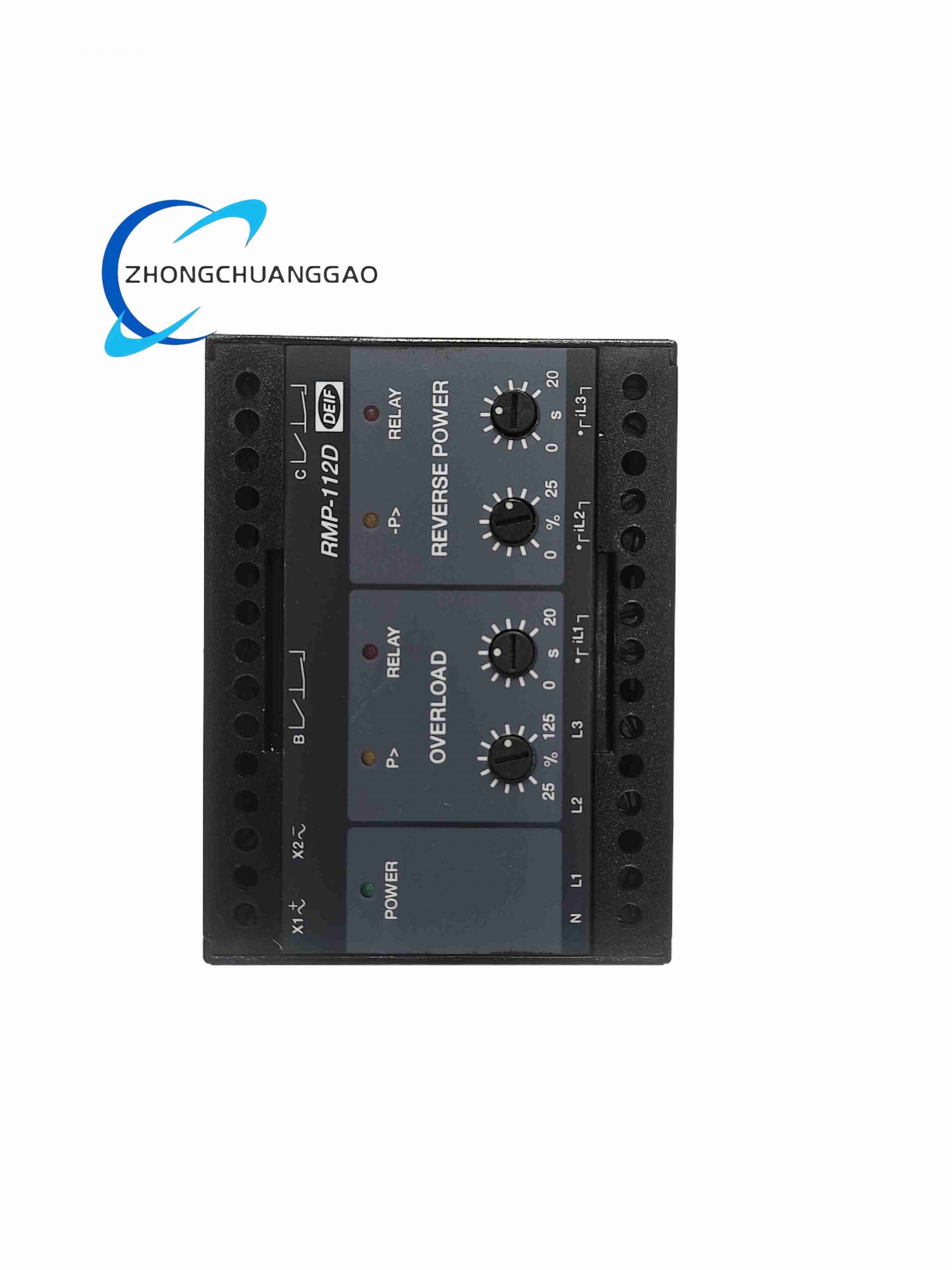
- Overload Protection Setting Range: 25% – 125% of generator rated power
- Reverse Power Protection Setting Range: 0% – 25% negative power (anti-motoring)
- Hysteresis Band: 2% of full measurement scale to prevent relay chattering
- Adjustable Trip Delay Timer: 0–20 seconds independent delay for overload and reverse power fault
- Response Speed: Maximum 400 ms fault detection response time
Electrical Measurement Spec
- Supported Network: Three-phase AC generator system
- Rated Measuring Voltage: 440 V AC max, 400 V AC nominal marine generator standard
- Current Transformer Secondary Input: 5 A standard CT secondary signal
- Auxiliary Supply Voltage Options: 110 V AC / 230 V AC / 24 V DC optional
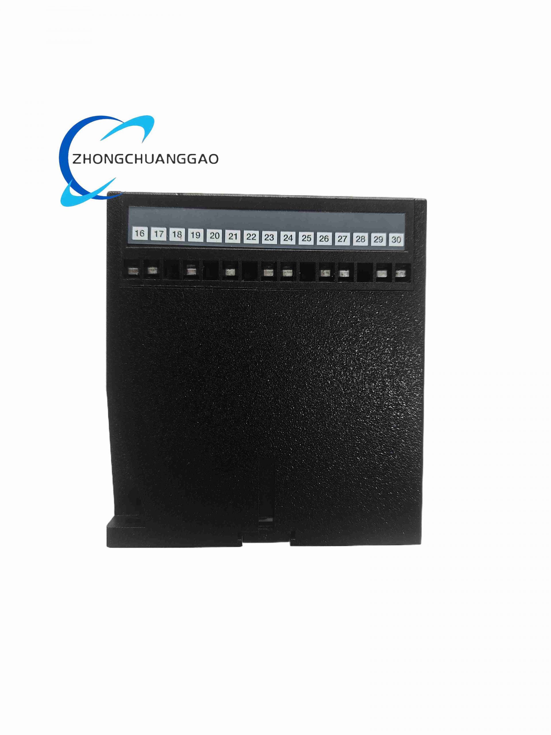
- Relay Output Contacts: Two independent mechanical relay outputs (Overload relay B, Reverse power relay C)
- Contact Rating: 250 V AC / 24 V DC, 8 A resistive load per contact
- Contact Mechanical Service Life: 200,000 switching operations under rated resistive load
Environmental & Mechanical
- Operating Ambient Temperature: -25 °C to +70 °C continuous operation; UL certified max 60 °C
- Temperature Drift Error: Max 0.2% full scale per 10 °C temperature variation
- Input-output Isolation Strength: 3250 V AC 50 Hz one minute withstand isolation
- Mounting Standard: 35 mm standard DIN rail mounting
- Protection Class: IP20 front panel, cabinet installation only
- Net Weight: 0.63 kg
Function & Feature Highlights
- Dual integrated protection functions in single compact module: generator overload protection and reverse power anti-motoring protection
- Independent adjustable delay timers for two fault types to eliminate nuisance tripping from transient power fluctuation
- Front panel rotary potentiometers for direct on-site threshold calibration without software configuration
- Independent LED status indicators for power supply, overload fault, reverse power fault for rapid on-panel fault diagnosis
- High isolation between measurement CT circuit, auxiliary supply and relay output contact circuits to avoid ground loop interference
- Marine vessel type approved, fully compliant with DNV, ABS marine generator safety standard
- Wide auxiliary supply voltage options compatible with land and marine generator control panel power systems
- Relay contact configurable as normally energized or normally de-energized via internal wiring jumper for flexible safety interlock design
Working Principle
- Three-phase voltage and CT secondary current signals from generator main circuit are input to internal precision power measurement circuit.
- Real-time three-phase active power calculation continuously compares measured power value against user-adjusted overload and reverse power threshold settings.
- If forward power exceeds overload setpoint or negative reverse power exceeds anti-motoring threshold, internal timer starts timing according to configured delay value.
- When delay timer completes countdown, corresponding mechanical relay contact pulls in to trigger generator circuit breaker trip signal or prime mover shutdown interlock circuit.
- Front panel LED illuminates to indicate active fault condition; fault status remains latched until generator power load recovers to normal safe operating range.
Material & Structural Composition
- Front Panel: Impact resistant black ABS plastic with transparent LED viewing window and calibration potentiometer access holes
- Main Housing: Flame-retardant plastic DIN rail mounting housing
- PCB Substrate: FR4 fiberglass circuit board, conformal anti-humidity coating for marine cabinet environment
- Measurement Components: High precision voltage/current sampling transformers, wide temperature range operational amplifiers
- Output Components: Sealed electromagnetic mechanical relays with arc suppression diodes
- Calibration Parts: Multi-turn carbon film precision rotary potentiometers
- Terminal Blocks: Nickel-plated copper screw terminals with stainless steel locking screws
Installation Requirements
- Standard 35 mm top-hat DIN rail vertical mounting inside generator control panel cabinet
- Maintain minimum 10 mm horizontal clearance between adjacent relay modules for heat dissipation
- CT secondary wiring must adopt dedicated shielded twisted pair cable, CT circuit strictly prohibited from open-circuit live operation
- Three-phase voltage measurement wiring must match generator phase sequence correctly; wrong phase sequence causes power measurement inversion error
- Auxiliary supply wiring must connect to stable uninterruptible control power source, avoid voltage fluctuation during generator startup
Application Scenarios
- Ocean-going vessel diesel generator parallel operation control panels
- Land-based backup emergency generator set protection cabinet
- Offshore platform auxiliary power genset safety monitoring system
- Hospital, data center critical backup generator protection
- Marine yacht and passenger ship power management system
Operation & Maintenance Precautions
- CT secondary circuit must never be disconnected while generator is running; open CT circuit generates dangerous high voltage and burns module internal sampling transformer
- Calibration potentiometer adjustment must be completed under generator no-load stable operating state for accurate threshold setting
- Avoid installation adjacent to high-current contactors and frequency drives to reduce electromagnetic interference affecting power measurement accuracy
- Conduct annual calibration of protection threshold setting with three-phase power standard calibrator to eliminate long-term drift error
- Relay contact load must not exceed rated 8 A resistive load; inductive trip coil loads require external surge absorption protection diode
-500x500.jpg)
Reviews
There are no reviews yet.