
Product Short Description
Product Overview
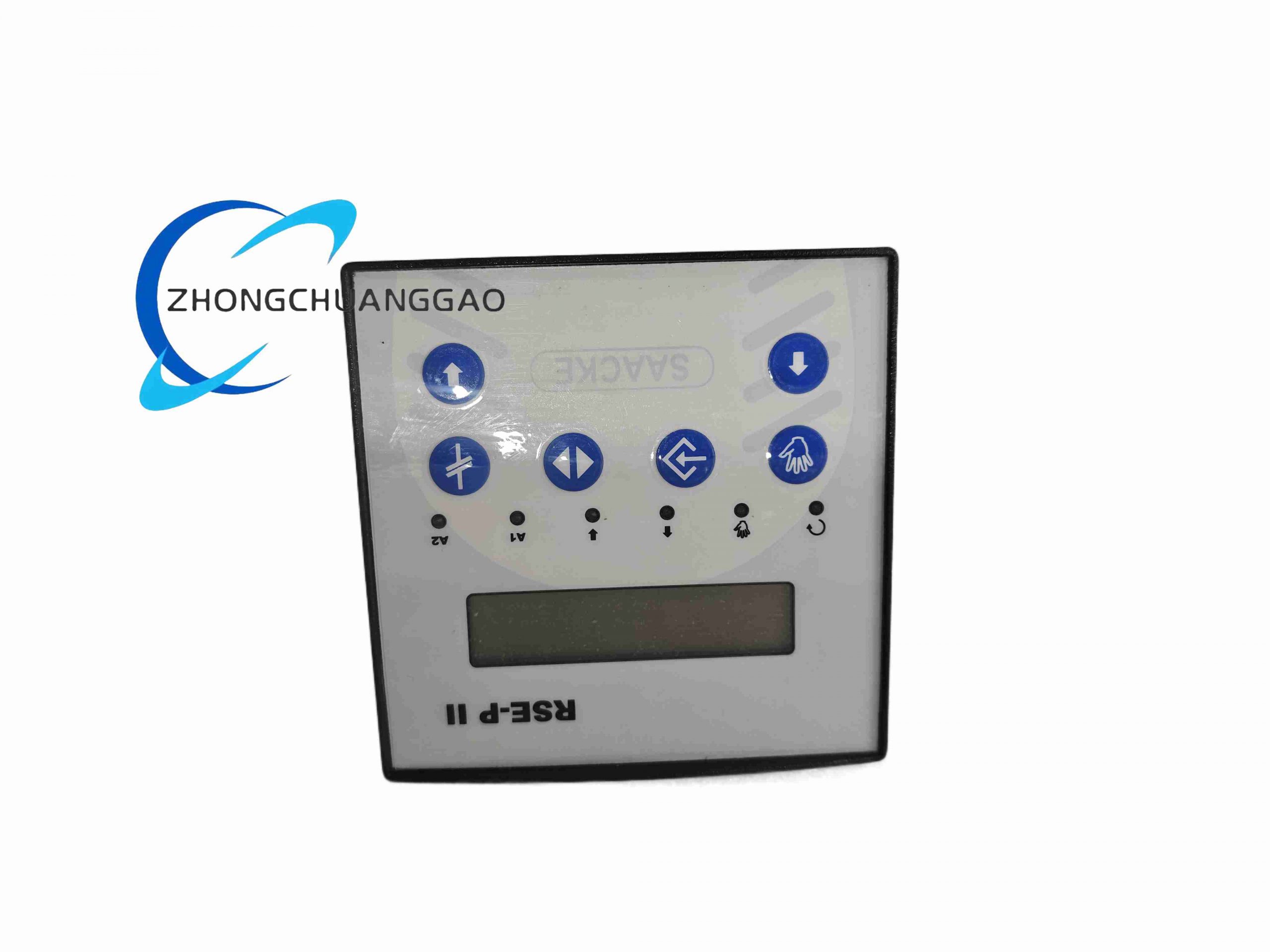
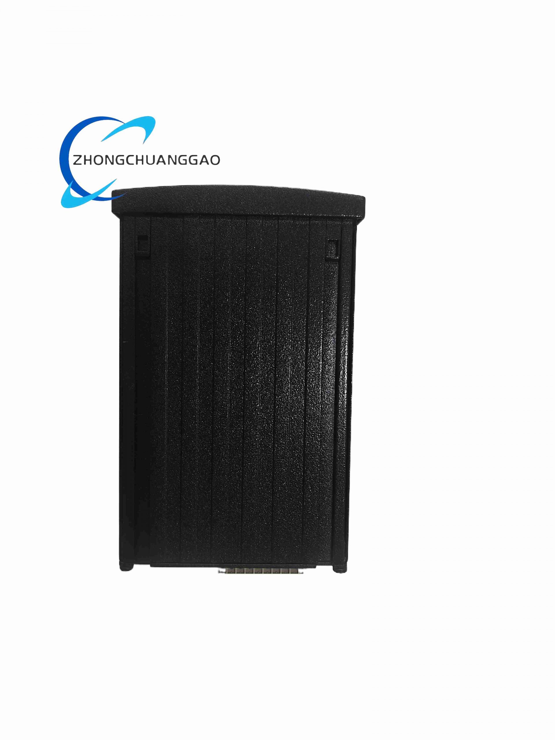
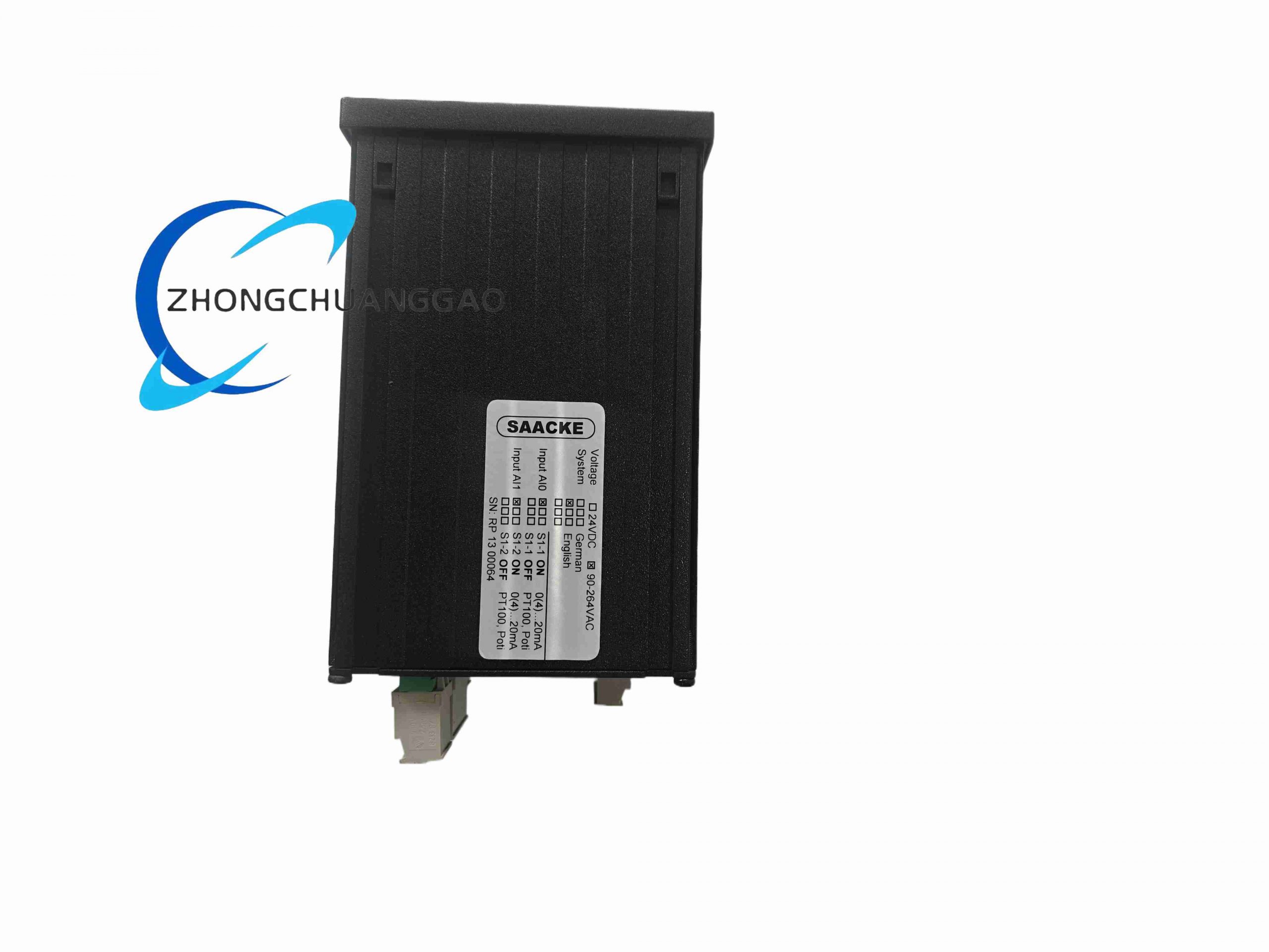
RSE-P II is a fully integrated safety burner logic controller independently developed by Germany SAACKE for industrial boilers, thermal furnaces, marine combustion systems and thermal processing kilns. This unit integrates automatic ignition sequence control, flame continuous monitoring, fuel-air ratio closed-loop adjustment, safety interlock protection, temperature PID regulation and fault event recording into one compact rack-mount module. It complies with EN 298, IEC 61508 SIL2 safety standards and marine classification society certifications including DNV, LR, ABS, supporting single-fuel gas burners, light/heavy oil burners and dual-fuel mixed combustion equipment.
Description
Core Technical Specifications
- Power Supply: Universal AC 90–264V 50/60Hz; optional redundant 24VDC backup power supply
- Rated Power Consumption: Static 12W, peak startup power 25W
- Digital I/O Configuration: 16 galvanic isolated digital inputs, 16 relay digital outputs; expandable to 64 I/O via SAACKE IO extension modules
- Analog Input Channels: 2 universal configurable analog input ports, compatible with 4–20mA transmitters, Pt100 thermal resistors, 0–10V potentiometer signals
- Flame Detection Interfaces: Dual independent UV flame scanner channels, single IR infrared flame sensor interface, supports triple redundant flame safety verification
- Safety Trip Execution Speed: Flame loss emergency fuel cut-off response time ≤500ms; system signal scan cycle ≤100ms
- Built-in Communication Ports: Profibus DP slave interface, Modbus TCP/IP Ethernet port, RS485 local service debugging port
- Supported Combustion Modes: Natural gas, liquefied gas, light fuel oil, heavy fuel oil, dual gas-oil mixed combustion
- Onboard Data Storage: 8MB flash memory, stores up to 50,000 combustion fault, startup and shutdown event logs with millisecond timestamps
- Operating Ambient Temperature: -30°C ~ +70°C; storage temperature: -40°C ~ +80°C
- Humidity Tolerance: 5%–95% RH non-condensing
- Vibration Resistance: 5–100Hz, 0.7g continuous vibration load
- Mounting Type: Standard 19-inch 3U rack installation
- Enclosure Protection Grade: IP30 cabinet internal use
- Overall Dimension: 483mm (W) × 133mm (H) × 210mm (D)
- Net Weight: 3.9kg
Functional Features
- Full automatic standardized ignition safety sequence: pre-purge, ignition delay, flame stabilization confirmation, fuel valve gradual opening, fully compliant with European combustion safety standards
- Dual independent flame signal acquisition circuits; system triggers immediate fuel cutoff if both flame sensors lose signal simultaneously
- Self-adaptive fuel-air ratio PID closed-loop control, automatically adjusts air damper and fuel valve output to maintain optimal combustion efficiency and reduce NOx emissions
- Comprehensive multi-layer safety interlock logic: low gas pressure, high gas pressure, low oil pressure, furnace over-temperature, air fan failure, flame loss, emergency stop hardwire interlock
- Complete hardware self-diagnosis circuit: power undervoltage, I/O channel short/open circuit, flame sensor failure, communication bus disconnection, with coded fault alarm output
- Large front panel LCD touch display for on-site parameter modification, real-time combustion data viewing, fault code inquiry without external configuration computer
- Redundant communication bus design; automatic communication channel switchover to avoid SCADA data loss during single line failure
- Hardwired emergency stop safety circuit independent of main CPU, achieves mechanical fuel cut-off even when controller main board fails
- Remote firmware upgrade and parameter batch download via Ethernet, supports offline configuration file backup and restoration
- Marine-grade anti-corrosion circuit coating, suitable for high humidity, salt spray ship engine room operating environments
Working Principle
After receiving furnace startup trigger signal, the controller first executes fixed-time air pre-purge program to exhaust residual unburned fuel inside the furnace via fan feedback signal verification. Once pre-purge cycle completes, the unit outputs high-voltage ignition transformer drive signal and opens pilot fuel valve; flame sensors continuously collect ultraviolet/infrared flame radiation signals and transmit feedback to main control MCU. The MCU judges flame stability via signal amplitude threshold; if valid flame signal is detected within safety ignition window, main fuel valve opens step by step. Real-time furnace temperature, air flow and fuel pressure analog signals are sampled and calculated by internal PID algorithm to adjust air damper and fuel actuator output, maintaining stable combustion ratio. If flame signal disappears, fan stalls or process parameters exceed safety threshold, independent hardware safety circuit immediately cuts all fuel valve power within 500ms and locks system until manual reset. All operation and fault data are timestamped and stored in onboard flash memory for later maintenance audit.
Material Composition & Structural Characteristics
- Cabinet Housing: Cold rolled steel plate with electrostatic anti-rust black coating, salt spray resistant surface treatment for marine applications
- Main Control PCB: FR-4 high Tg flame retardant circuit board with full acrylic conformal coating against moisture and salt fog corrosion
- Terminal Blocks: PA66 flame retardant plastic terminals, nickel-plated copper conductive terminals with spring anti-loosening structure
- Flame Signal Isolation Components: High voltage isolation optocouplers, signal filtering inductors to suppress furnace electromagnetic interference
- Display Module: Industrial wide temperature LCD touch screen with anti-glare protective glass panel
- Heat Dissipation Design: Passive convection vent slots on upper and lower cabinet panels, fanless design to eliminate fan failure points
- Internal Layout Separation: Independent compartment layout for power circuit, flame detection signal circuit and communication bus circuit to reduce cross interference
Application Scenarios
- Industrial heating furnaces, metal heat treatment kilns gas/oil combustion control
- Central heating large gas-fired and oil-fired hot water boilers
- Marine ship auxiliary boilers, engine room thermal oil furnace combustion safety control
- Paper mill drying line high-temperature combustion heating systems
- Petrochemical plant process heating furnace burner management
- Food processing factory thermal processing steam boiler control systems
Installation Requirements
- Install in standard 19-inch sealed industrial control cabinet, reserve minimum 100mm upper and lower vertical space for convection heat dissipation
- Separate flame sensor signal wiring from high-voltage ignition cable, maintain minimum 40cm laying distance to avoid signal interference
- All signal cables adopt shielded twisted pair, shield layer single-point grounding at cabinet earth bar with 4mm² copper grounding wire
- Cabinet must be equipped with temperature control exhaust fan if ambient operating temperature exceeds 55°C
- Marine installation requires additional anti-vibration DIN rail fixing accessories to resist hull continuous vibration
- Emergency stop hardwire circuit must use independent dedicated cable without sharing wiring with other control signals
- Flame scanner signal wiring length shall not exceed 50 meters to prevent flame signal attenuation and false flameout alarms
Operation & Maintenance Precautions
- Strictly cut off all power supply before disassembling front panel wiring terminals; live wiring may damage flame detection isolation circuits
- Clean front LCD screen dust and oil stains monthly with soft lint-free cloth, avoid corrosive chemical cleaning agents
- Export historical fault logs every two months for regular combustion system safety inspection and maintenance records
- Replace UV flame scanner probes every 2 years; UV glass window aging will cause inaccurate flame detection
- Do not modify internal safety interlock program logic without SAACKE official professional authorization, which will invalidate SIL2 safety certification
- Firmware upgrade must maintain stable continuous power supply; power interruption during upgrade will cause program loss and system lockout
- In coastal high salt spray environment, clean cabinet internal PCB surface dust and salt accumulation every 6 months to prevent circuit short circuit
Reviews
There are no reviews yet.