
Product Short Description
Product Overview
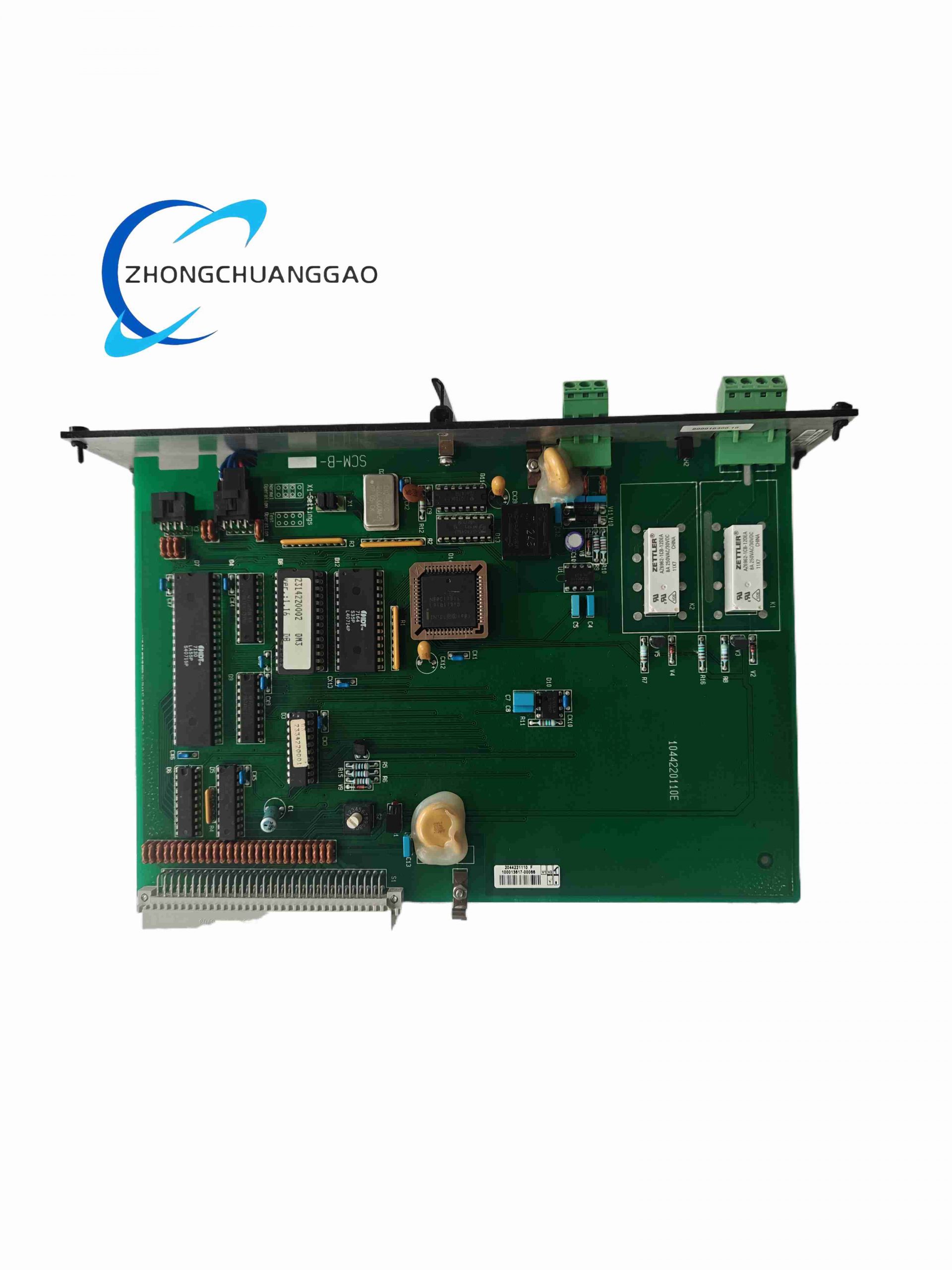
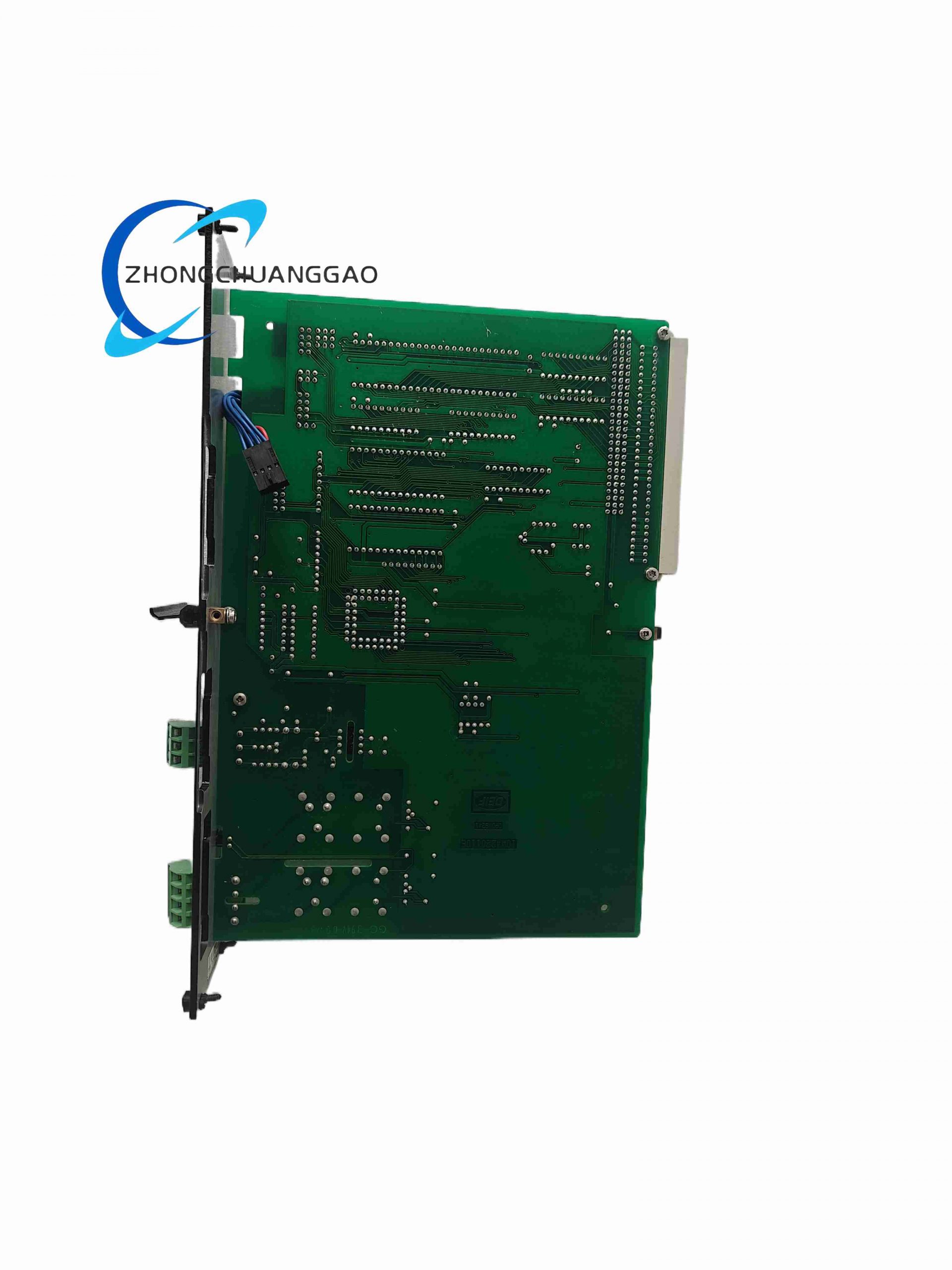
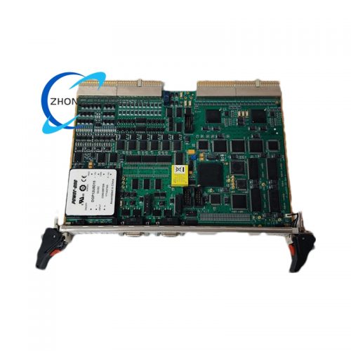
The SCM-2 is a multi-functional signal conditioning and logic control module manufactured by DEIF Denmark for the Delomatic 3 distributed generator control system, specifically designed for marine vessel power plants, offshore platforms, and stationary diesel generator parallel control systems. Model 1044220110E is the standard universal signal version supporting analog sensor signal conversion, digital logic interlock, alarm processing, and bus communication with other Delomatic 3 system modules including IPM-1, OPM-1, PSM-1. It processes generator voltage, current, temperature, pressure sensor signals and executes protective interlock logic for genset safety control.
Description
Core Technical Specifications
- Auxiliary Power Supply: 24 V DC nominal (operating range 18 V DC to 32 V DC marine battery bus)
- Analog Input Channels: 8 universal analog input channels (0–10 V DC, 4–20 mA, PT100 temperature sensor compatible)
- Digital Input Channels: 16 opto-isolated digital binary inputs (12–24 V DC active high signal level)
- Relay Output Channels: 8 mechanical relay outputs (5 A / 250 V AC resistive load rating)
- Internal Communication Bus: DEIF Delomatic 3 proprietary serial backplane bus for system module interconnection
- Signal Isolation Level: 1500 V AC isolation between field sensor circuits and internal logic power
- Operating Ambient Temperature: -25 °C to +70 °C marine wide temperature range
- Humidity Tolerance: 5% RH to 95% RH non-condensing marine atmosphere
- Protection Rating: IP20 front panel, fully enclosed PCB with conformal coating
- Mounting Standard: 19-inch rack subrack plug-in module (6 U height single slot form factor)
- Module Weight: 0.78 kg
Functional Features
- Multi-Type Analog Signal Conditioning: Onboard configurable jumpers switch each analog channel between voltage, current, and PT100 resistance temperature input without external signal converters
- Programmable Alarm Threshold Logic: Each input channel supports independent high/low threshold alarm, delay timer (0–300 s adjustable), and relay output assignment for genset fault alarms (high coolant temp, low oil pressure, overvoltage)
- Generator Interlock Logic Execution: Built-in boolean logic processor executes parallel genset interlock, load sharing enable, and breaker close/block interlock conditions
- Conformal Coated PCB Design: Entire circuit board coated with acrylic conformal coating to resist marine salt fog, moisture, and mild chemical vapor corrosion
- System Fault Diagnostics: Front panel LED indicators for power status, bus communication fault, channel open-circuit sensor fault, relay active status
- Parameter Non-Volatile Storage: All alarm thresholds, signal scaling factors, and logic configurations stored in EEPROM memory, retained indefinitely without backup power
Material Composition
- Module Front Panel: ABS flame-retardant plastic with silk-screened channel label marking
- Module Chassis Frame: Galvanized cold-rolled steel anti-rust frame for rack plug-in mechanical support
- Main Circuit PCB: FR4 flame-retardant printed circuit board with full acrylic conformal coating
- Input/Output Terminal Blocks: PA66 glass-reinforced plastic with tin-plated copper screw terminals
- Electromechanical Relays: Silver alloy contact relays with sealed dust-resistant housing
- Opto-Isolator Chips: High-speed linear optocoupler semiconductor components for signal isolation
Structural Characteristics
- Hot-swappable plug-in subrack module design; can be removed and replaced without full system power shutdown
- Layered internal layout: Front terminal wiring compartment, middle analog signal processing PCB, rear backplane communication connector
- Dual terminal strip layout: Upper terminals for analog sensor wiring, lower terminals for digital input and relay output wiring to separate low-level and power signals
- Locking plastic latch on front panel to secure module into subrack rack and prevent vibration loosening during marine vessel operation
- Integrated EMC filter circuits at all field wiring terminals to suppress vessel power system surge and noise interference
Working Principle
- 24 V DC marine battery auxiliary power supplies internal digital logic and analog signal processing circuits
- Field sensor signals (PT100 coolant temperature, 4–20 mA oil pressure, generator voltage transducers) connect to analog input terminals; onboard op-amp circuits scale raw sensor signals to internal 0–5 V reference measurement range
- Opto-isolator circuits decouple digital input binary signals from marine vessel ground potential differences to eliminate ground loop measurement error
- Internal 16-bit microcontroller samples all analog and digital input channels at 100 ms scan cycle, compares measured values against user-programmed alarm thresholds
- If measured value crosses threshold with configured delay timer expired, microcontroller triggers corresponding mechanical relay output to activate alarm horn, genset shutdown interlock, or breaker trip signal
- Processed measurement data and fault status transmit via Delomatic 3 backplane serial bus to master control modules for genset parallel load sharing and HMI display data upload
Application Scenarios
- Commercial cargo ship main generator parallel control systems
- Offshore oil & gas platform diesel genset monitoring and protection cabinets
- Marine yacht emergency backup generator automation panels
- Land-based distributed diesel generator power station parallel control
- Construction site temporary heavy-duty generator monitoring control cubicles
Installation Requirements
- Install inside IP44+ sealed marine electrical subrack cabinet with anti-vibration rack mounting brackets for vessel shock absorption
- Separate analog sensor cable routing from high-current generator breaker power cables; minimum 40 cm wiring separation distance
- All field wiring cable shielding connected to cabinet protective earth ground bar at single termination point to avoid ground loops
- Maintain minimum 10 mm vertical clearance above and below module slot for internal convection cooling
- Subrack cabinet must be fitted with heating element for operation in ambient temperatures below -10 °C to prevent PCB condensation
- Backplane communication bus wiring must use DEIF specified shielded twisted pair bus cable only
Operation & Maintenance Precautions
- Prior to module hot-swap replacement, confirm no critical genset interlock logic relies on SCM-2 relay outputs to avoid unplanned generator shutdown
- Conduct annual salt fog inspection for marine installations; wipe terminal block corrosion with isopropyl alcohol and re-torque all wiring screws
- PT100 analog channel open-circuit fault alarm must be tested quarterly by disconnecting temperature sensor wiring
- Do not apply input signal voltage exceeding 12 V DC to digital input terminals; overvoltage destroys opto-isolator semiconductor chips
- Mechanical relay contact wear limits relay load to resistive loads only; install external auxiliary contactor for inductive alarm horn loads
- Avoid cabinet installation locations with direct engine exhaust heat radiation exceeding +70 °C ambient temperature limit
Reviews
There are no reviews yet.