
Product Short Description
Product Overview
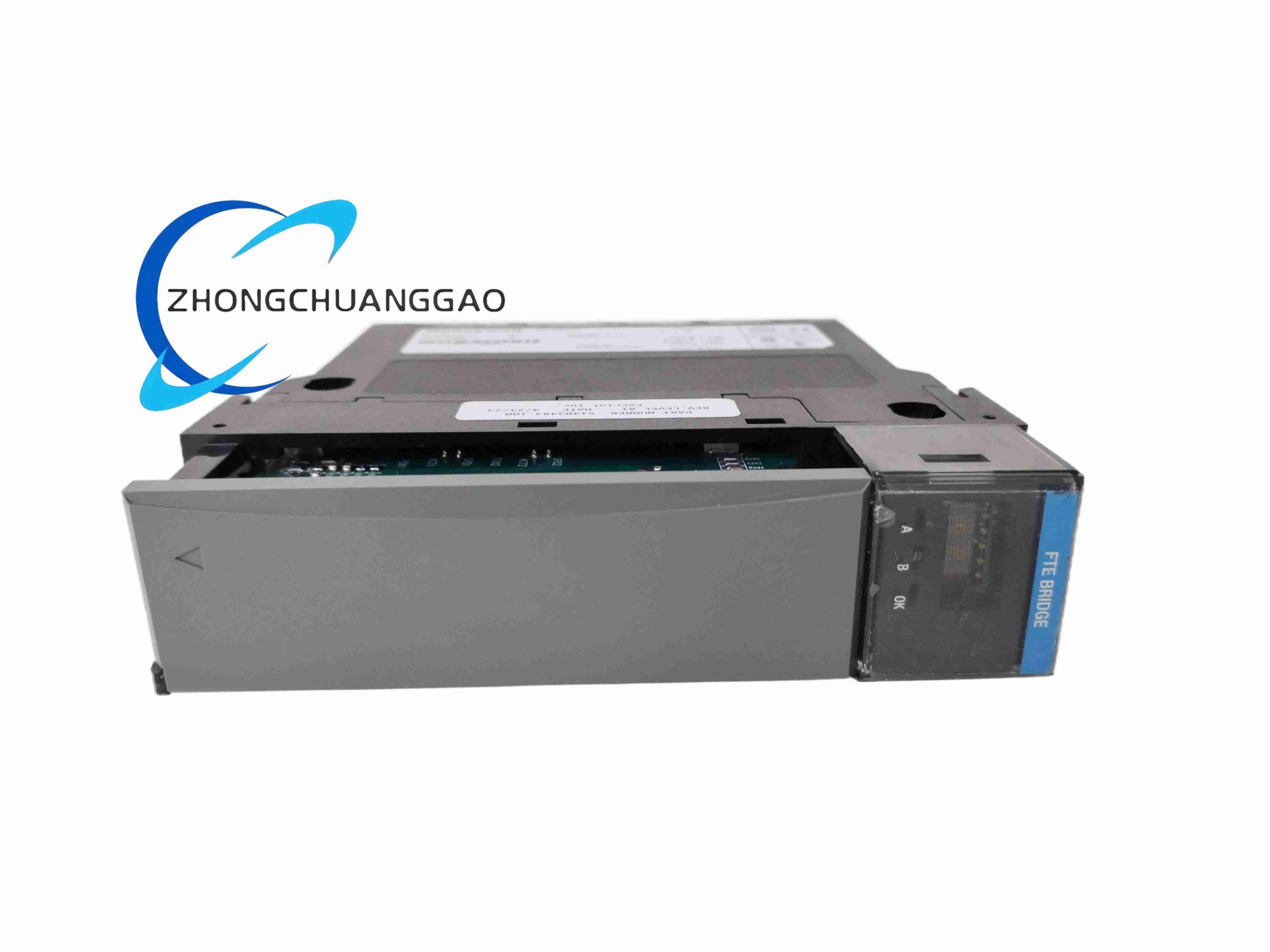
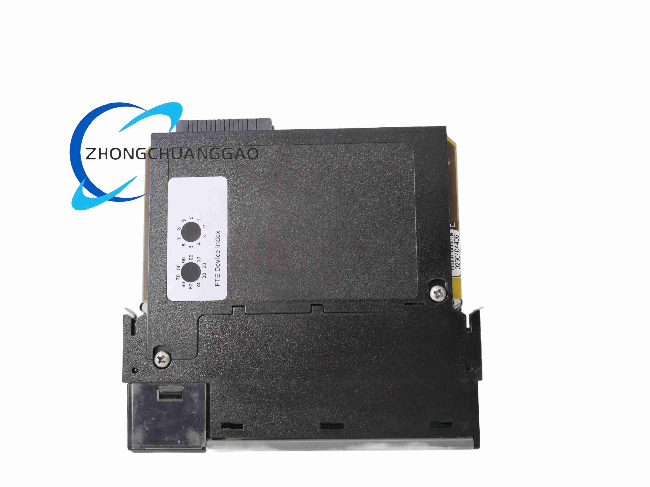
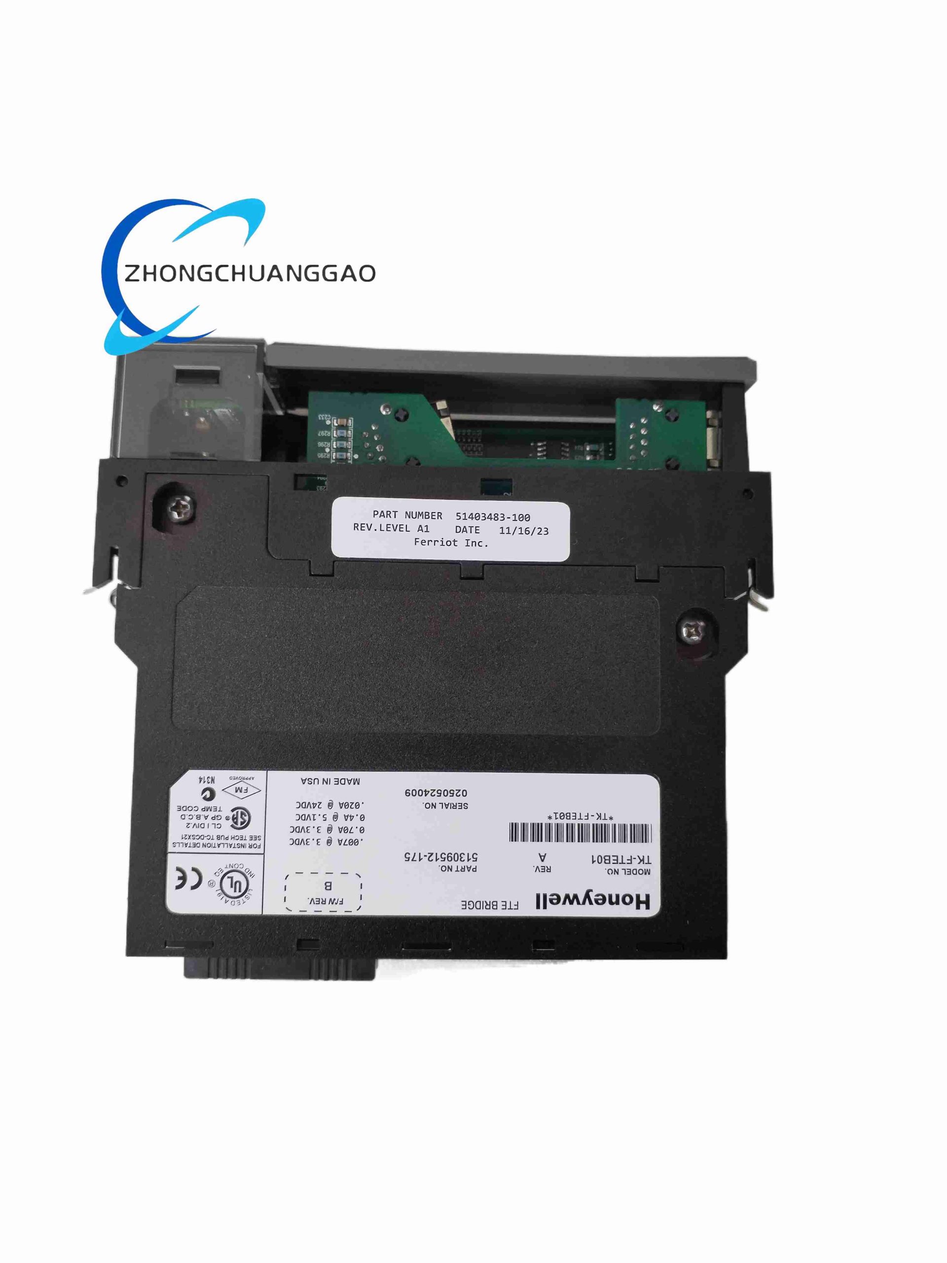
TK-FTEB01 is the dedicated fault tolerant Ethernet communication interface module for Honeywell Experion PKS C300 DCS control racks, implementing Honeywell proprietary FTE redundant industrial Ethernet protocol. It connects the C300 control rack backplane to dual redundant plant control network switches, eliminating single network cable or switch point of failure for critical process control data, alarm events and historical trend transmission between field controllers and operator stations.
Description
Core Technical Specifications
- Communication Protocol: Honeywell FTE Fault Tolerant Ethernet (IEEE 802.3 10/100Mbps Fast Ethernet)
- Physical Ports: Dual RJ45 shielded Ethernet ports (Port A / Port B redundant network links)
- Backplane Bus: C300 proprietary redundant control rack backplane interface
- Redundancy Switchover Time: ≤20ms automatic link failover between dual Ethernet ports
- Supported Upper System Devices: Experion Server, Operator Stations, FTE Network Switches, Safety Manager Controllers
- Maximum Network Cable Distance: 100m Cat5e twisted pair per Ethernet port
- Operating Power Supply: 24VDC, 150mA typical module power draw
- Operating Temperature: -20°C to +60°C operational; -40°C to +85°C storage
- Humidity Range: 5%–95% RH non-condensing
- EMC Compliance: IEC 61000-6-2 industrial heavy electromagnetic environment standard
- Physical Dimensions: 130(H) × 105(W) × 32(D) mm
- Net Weight: 380g
Key Functional Features
- Dual independent FTE Ethernet communication channels with automatic link failover; data transmission uninterrupted upon single port/cable/switch failure
- Proprietary FTE network packet mirroring and validation logic to eliminate duplicate process data transmission errors
- Full two-way communication between C300 rack TC-PRS021 processor and upper-level Experion control network
- Comprehensive network diagnostics: link loss, packet loss rate, communication latency, switch port fault, backplane bus communication failure monitoring
- Hot-swappable rack mount design; module replacement without full control rack power shutdown
- Built-in network fault event timestamp logging stored in non-volatile memory for plant network audit
- Isolated Ethernet PHY circuits with ±15kV ESD surge protection for industrial cabinet wiring environments
Working Principle
24VDC rack power energizes dual independent Ethernet PHY transceivers and backplane communication processing unit inside TK-FTEB01. Process data, alarm signals and historical trend data from TC-PRS021 processor transmit via C300 backplane bus to the FTE processing core. The core duplicates all data packets and transmits identical frames simultaneously through Port A and Port B dual Ethernet links to separate redundant FTE network switches. Receiving side network equipment validates duplicate packets and discards redundant frames to avoid duplicate data at operator stations. If one Ethernet port loses link signal, the module instantly switches all data transmission to the remaining healthy port within 20ms without process data interruption. Continuous diagnostic circuits monitor packet transmission latency, error frame count and physical link status; abnormal network conditions trigger rack system fault alarms visible on Experion operator station HMI displays.
Material Composition & Structural Characteristics
- Outer Housing: UL94-V0 flame retardant anti-static black polycarbonate alloy, industrial rack form factor
- Main PCB: Multi-layer FR-4 fiberglass substrate with isolated Ethernet signal routing zones, gold-plated backplane edge connectors
- Network Interface Components: Dual isolated 10/100Mbps Ethernet PHY chips with integrated surge protection circuits
- Port Connectors: Shielded RJ45 Ethernet jacks with integrated LED link/activity status indicators
- Indicator Panel: Multi-color LED array showing power, backplane communication, Port A link, Port B link, module fault status
- Internal Hardware: Industrial real-time communication microcontroller, non-volatile flash memory for fault log storage, isolated DC-DC power converters for Ethernet transceivers
Installation Requirements
- Mount on Honeywell C300 series control rack backplane dedicated FTE module slot positions
- Maintain minimum 15mm vertical ventilation gap between adjacent rack modules to prevent overheating of Ethernet transceivers
- Ethernet communication cables must use Cat5e shielded twisted pair wiring with single-ended shield grounding at cabinet earth bar
- Each RJ45 port wired to separate independent FTE network switch to achieve full dual redundant network architecture
- Rack protective earth grounding resistance ≤4Ω to maximize EMC surge protection performance
- Avoid mounting control rack near high-power variable frequency drives to reduce network electromagnetic interference
- Front panel LED link status indicators must remain unobstructed for daily network health inspection
Typical Application Scenarios
- Refinery & petrochemical plant C300 DCS main control rack network interface
- Natural gas processing plant redundant FTE control network communication modules
- Power plant thermal unit boiler/turbine DCS rack Ethernet interface
- Chemical batch manufacturing distributed control system redundant network bus
- Pulp & paper mill process control rack fault tolerant Ethernet communication
- Municipal large-scale water treatment plant DCS redundant network interface racks
Operation & Maintenance Precautions
- Disconnect both Ethernet RJ45 cables before hot-swapping the TK-FTEB01 module to eliminate transient network surge voltage damage
- Review module network fault logs weekly to identify deteriorating Ethernet cable or switch port performance
- Clean cabinet air intake filters every 3 months to maintain cooling airflow and prevent dust accumulation on PCB Ethernet circuits
- Spare TK-FTEB01 modules must be stored in ESD anti-static packaging at stable 10–30°C ambient temperature
- Unauthorized disassembly of module housing voids Honeywell factory DCS system certification
- After module replacement, conduct full dual-link failover test to verify seamless network switchover performance before restoring full plant process operation
- Separate FTE Ethernet wiring from high-voltage AC power cables by minimum 30cm distance to avoid packet loss communication faults
8. Yokogawa TLC411F
Product Full Name
Yokogawa TLC411F Analog Output Control Module (Centum VP DCS Series)
Product Overview
TLC411F is a high-precision isolated analog output module designed for Yokogawa Centum VP distributed control systems, responsible for converting digital control setpoint signals from the FCU field control unit into standard 4–20mA analog output signals to drive field control valves, variable frequency drives and proportional actuators. It features multi-channel galvanic isolation, high linearity conversion and comprehensive channel fault diagnostics for continuous process control in chemical, oil & gas and power industry DCS racks.
Core Technical Specifications
- Channel Count: 8 isolated analog output channels
- Standard Output Signal: 4–20mA DC two-wire analog control signal
- Output Accuracy: ±0.04% full scale at 25°C; ±0.12% full scale over full operating temperature range
- Conversion Resolution: 16-bit digital-to-analog converter per independent channel
- Channel Isolation: 500VDC galvanic isolation between each channel group and backplane bus
- Maximum Loop Load Resistance: 750Ω per output channel
- Update Cycle: 10ms full 8-channel output refresh cycle
- Backplane Bus: Centum VP proprietary FCU redundant backplane communication bus
- Operating Power Supply: 24VDC, 145mA typical module consumption
- Operating Temperature: 0°C to +60°C operational; -30°C to +75°C storage
- Humidity Range: 5%–90% RH non-condensing
- Physical Dimensions: 129(H) × 110(W) × 33(D) mm
- Net Weight: 395g
Key Functional Features
- 8 independent 4–20mA analog output channels with individual 16-bit DAC conversion for high-precision valve positioning control
- Full channel isolation prevents cross-channel interference and ground loop distortion of analog output signals
- Configurable fault-safe output state per channel (0mA / 4mA / 20mA hold last value) upon module or communication failure
- Comprehensive channel diagnostics: open loop, short circuit, over-load resistance, backplane communication loss detection
- Hot-swappable rack mount design; module replacement without Centum VP FCU controller shutdown
- Built-in digital low-pass filter configurable per channel to smooth output signal fluctuation for noisy process environments
- Non-volatile memory stores channel calibration offset parameters to maintain precision after power cycle or module replacement
Working Principle
Digital control setpoint values from the Yokogawa FCU field control unit transmit via redundant Centum VP backplane bus to the TLC411F internal processing core. Each digital setpoint value feeds a dedicated 16-bit DAC converter circuit, which generates a precision analog voltage reference signal converted to regulated 4–20mA loop current via isolated current drive stages. Galvanic isolation transformers separate each output channel from the backplane digital circuit to eliminate ground loop noise between the control rack and field actuators. Continuous load impedance monitoring circuits measure loop current and resistance; abnormal loop conditions trigger fault flags and force output to user-defined safe state to prevent hazardous process valve mispositioning. Calibration offset parameters stored in flash memory automatically compensate DAC drift across wide ambient temperature ranges to maintain consistent output accuracy.
Material Composition & Structural Characteristics
- Module Housing: Black UL94-V0 flame retardant polycarbonate alloy, anti-static coating for industrial cabinet EMC protection
- Main PCB: Double-layer high-temperature FR-4 fiberglass substrate with gold-plated backplane edge connectors
- Conversion Components: Low-drift precision voltage reference chips, independent 16-bit DAC converters per channel
- Isolation Hardware: Miniature reinforced isolation transformers separating analog output stages from digital backplane circuits
- Terminal Interface: Screw-clamp tin-plated copper terminal blocks for field 4–20mA actuator loop wiring
- Indicator Panel: Bi-color LED channel status indicators (green = normal output, red = channel fault) with scratch-resistant polycarbonate cover
Installation Requirements
- Mount exclusively on Yokogawa Centum VP FCU redundant control rack backplane single slot positions
- Maintain minimum 12mm vertical ventilation gap between adjacent modules to prevent thermal drift impacting analog output precision
- Field 4–20mA actuator wiring uses shielded twisted pair cables with single-ended shield grounding at cabinet earth bar
- Rack frame grounding resistance ≤4Ω to suppress ground loop interference on analog output signals
- Separate analog output wiring from high-current AC power cables by minimum 25cm distance to reduce induced noise
- Cabinet cooling airflow ≥0.6m/s across module front panel; maximum continuous ambient temperature limit 60°C
- Front LED indicator panel must remain unobstructed for daily channel fault inspection
Typical Application Scenarios
- Petrochemical plant control valve positioning analog output control racks
- Oil refinery furnace fuel gas flow regulation actuator drive modules
- Natural gas compressor station anti-surge valve signal output
- Power plant boiler feedwater & steam pressure control valve driving
- Fine chemical batch reactor temperature/pressure regulating valve control
- Water treatment plant pH adjustment dosing valve analog signal output
Operation & Maintenance Precautions
- Disconnect all field 4–20mA loop wiring before hot swapping the module to avoid DAC circuit damage from transient short-circuit currents
- Perform full channel linearity calibration every 18 months per Yokogawa DCS maintenance specifications
- Avoid cabinet environments with high humidity, chemical vapor or heavy dust; install intake air filter assemblies to prevent PCB contamination
- Spare TLC411F modules must be stored inside ESD anti-static packaging at stable 10°C to 35°C ambient temperature
- Internal PCB disassembly, component replacement or circuit modification without Yokogawa official authorization voids factory calibration certification and product warranty
- After module replacement, conduct full loop injection testing to verify 4–20mA output linearity and fault-safe state switching before restoring process automatic control
- Analog signal cables must be routed separately from high-voltage AC power, variable frequency drive power lines with a minimum separation distance of 25cm to eliminate electromagnetic signal distortion
Reviews
There are no reviews yet.