
Product Short Description
Product Overview
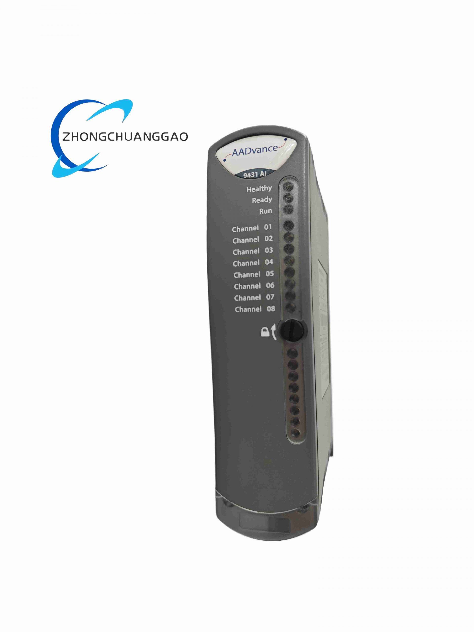
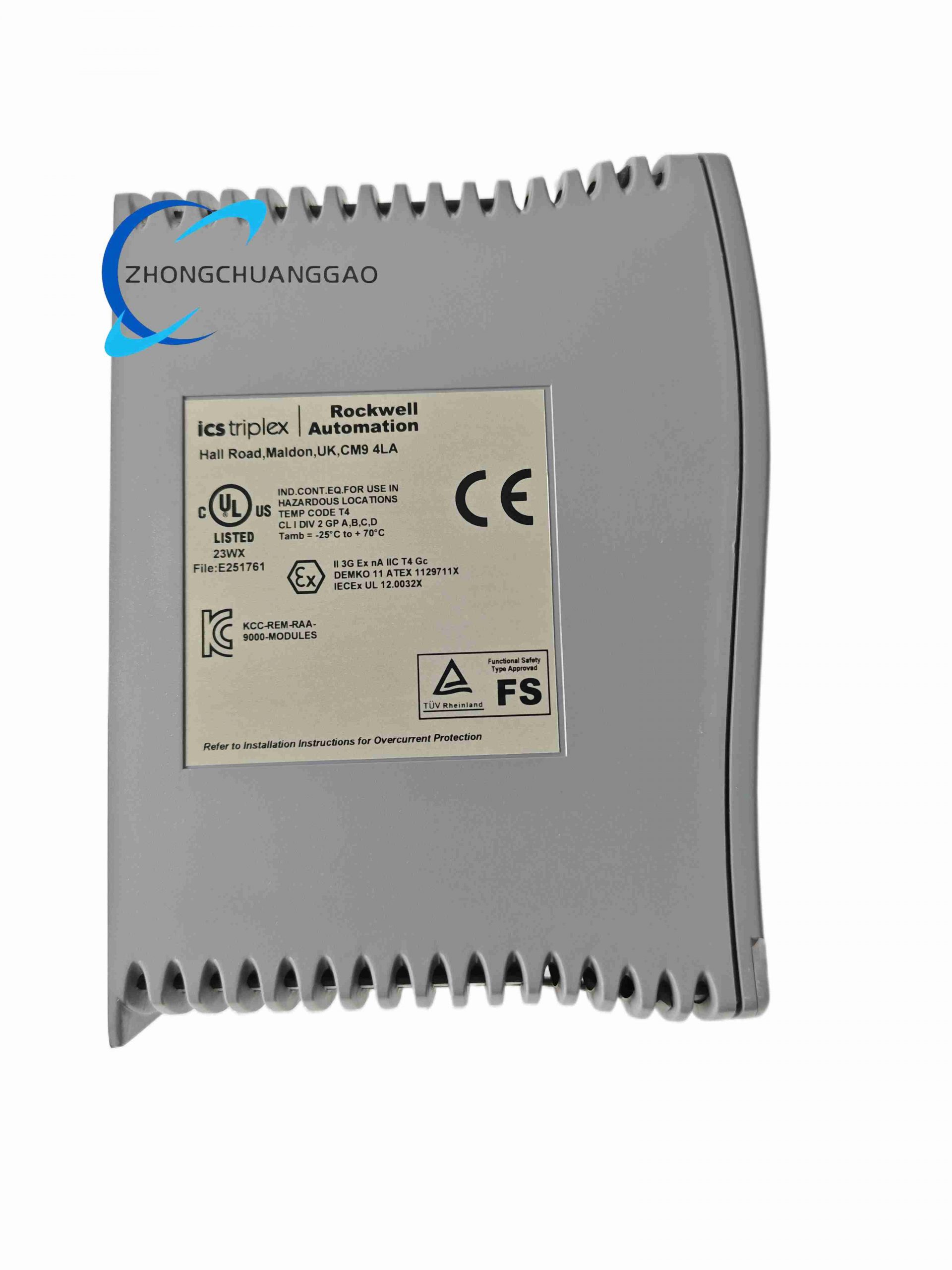
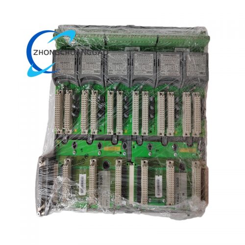
The T9431 is a triple modular redundant (TMR) safety-rated digital input module developed by ICS Triplex (Rockwell Automation Safety Division), designed for SIL 3 safety instrumented systems (SIS). It acquires discrete on/off field signals from switches, proximity sensors, limit valves and safety interlocks, performs triple-channel independent signal sampling, and transmits validated digital status to the T9402 main safety controller. It delivers fault-tolerant signal acquisition without process shutdown during single hardware failure.
Description
Core Technical Specifications
- Safety Integrity Level: SIL 3 certified per IEC 61508 / IEC 61511
- Channel Count: 32 isolated digital input channels
- Input Signal Type: 24VDC sinking/sourcing industrial discrete signals
- Input Voltage Range: 18VDC – 30VDC nominal operating
- Channel Isolation: 500VAC galvanic isolation per channel group
- Sampling Cycle: 8ms triple parallel sampling per channel
- Backplane Bus: T9000 proprietary safety redundant backplane
- Operating Power: 24VDC, max 180mA module consumption
- Environmental Temperature: -20°C to +70°C operational; -40°C to +85°C storage
- Humidity: 5%–95% RH non-condensing
- Vibration Resistance: 10–150Hz, 1g continuous per IEC 60068-2-6
- Shock Resistance: 15g peak, 11ms duration per IEC 60068-2-27
- Dimensions: 128mm (H) × 130mm (W) × 32mm (D)
- Net Weight: 420g
Key Functional Features
- Full TMR triple independent signal processing; three separate analog front-end circuits for every input channel, hardware voting logic eliminates single-point failure
- Comprehensive channel-level diagnostics: open circuit, short circuit, overvoltage, ground fault, backplane communication failure, internal power rail monitoring
- Hot-swappable design; module replacement without system power down or safety logic interruption
- Built-in fault latch & non-volatile fault event logging for post-failure audit
- Software-configurable channel debounce delay (0.5ms–100ms) to filter field contact bounce noise
- Channel group isolation prevents cross-channel short circuit propagation
- Conforms to ATEX, IECEx hazardous area control cabinet installation standards
Working Principle
Field 24VDC discrete signals enter each channel’s isolated optocoupler isolation stage, split into three identical independent signal acquisition paths inside the module. Each path samples the input state simultaneously within 8ms cycles. Three digital signal processors compare sampled values via hardware majority voting logic; only signals matched by at least two channels are recognized as valid input status. Mismatched channel data triggers instant diagnostic fault flags without invalidating overall channel state. Validated digital status packets are transmitted to the T9402 safety controller via redundant backplane communication bus. All internal power rails are triple-regulated to avoid single power supply failure.
Material Composition & Structural Characteristics
- Outer Housing: Flame-retardant UL94-V0 black polycarbonate alloy, anti-static, chemical resistant to industrial oil & solvent vapors
- Internal PCB: Double-sided high-temperature FR-4 fiberglass substrate with gold-plated signal traces, heavy copper power layers for thermal dissipation
- Isolation Components: High-speed optocoupler chips with reinforced insulation packaging
- Backplane Connector: Nickel-plated copper multi-pin edge connector with gold contact plating for low resistance long-term contact
- Indicator Panel: High-brightness bi-color LED array (green = normal, red = channel fault) covered by scratch-resistant polycarbonate window
- Internal Hardware: Triple independent low-power industrial-grade microcontrollers, surface-mount tantalum capacitors, precision metal film resistors
Installation Requirements
- Mount exclusively on T9000 series 19-inch rack redundant backplane slots; occupy single standard module slot
- Maintain minimum 15mm vertical ventilation gap between adjacent modules for heat dissipation
- Cabinet cooling airflow must be ≥0.8m/s across module front panel; avoid direct hot air recirculation
- Field wiring terminal blocks must be wired with shielded 24VDC twisted pair cables; cable shield grounded at cabinet single grounding bar only
- Grounding resistance of rack frame ≤4Ω to eliminate EMC interference
- For hazardous zone Class I Div 2 installation, cable glands must meet Ex d certification; no wiring live module terminals in explosive atmosphere
- Module front panel LED indicators must remain unobstructed for routine visual inspection
Typical Application Scenarios
- Oil & gas refinery safety interlock SIS systems
- Petrochemical plant emergency shutdown (ESD) control racks
- Power plant boiler & turbine safety protection logic
- Chemical batch reactor overpressure/overtemperature interlock systems
- Offshore platform safety instrumented control cabinets
- Fertilizer plant ammonia process safety monitoring
Operation & Maintenance Precautions
- Do not plug/unplug module when field 24VDC input circuits remain energized; disconnect field wiring prior to hot swap
- Avoid exposing module housing to direct liquid splash, corrosive gas or continuous dust accumulation; install cabinet air filtration
- Calibrate channel fault detection threshold every 24 months per safety maintenance schedule
- Store spare modules in anti-static ESD packaging at 10°C–30°C ambient temperature
- Never modify internal PCB components; unauthorized disassembly voids SIL safety certification
- After fault replacement, perform full channel loop test to verify signal acquisition integrity before restoring process operation
- Avoid routing high-current AC power cables parallel to module input signal wiring to prevent electromagnetic interference
Reviews
There are no reviews yet.