
Product Short Description
Product Brief Introduction
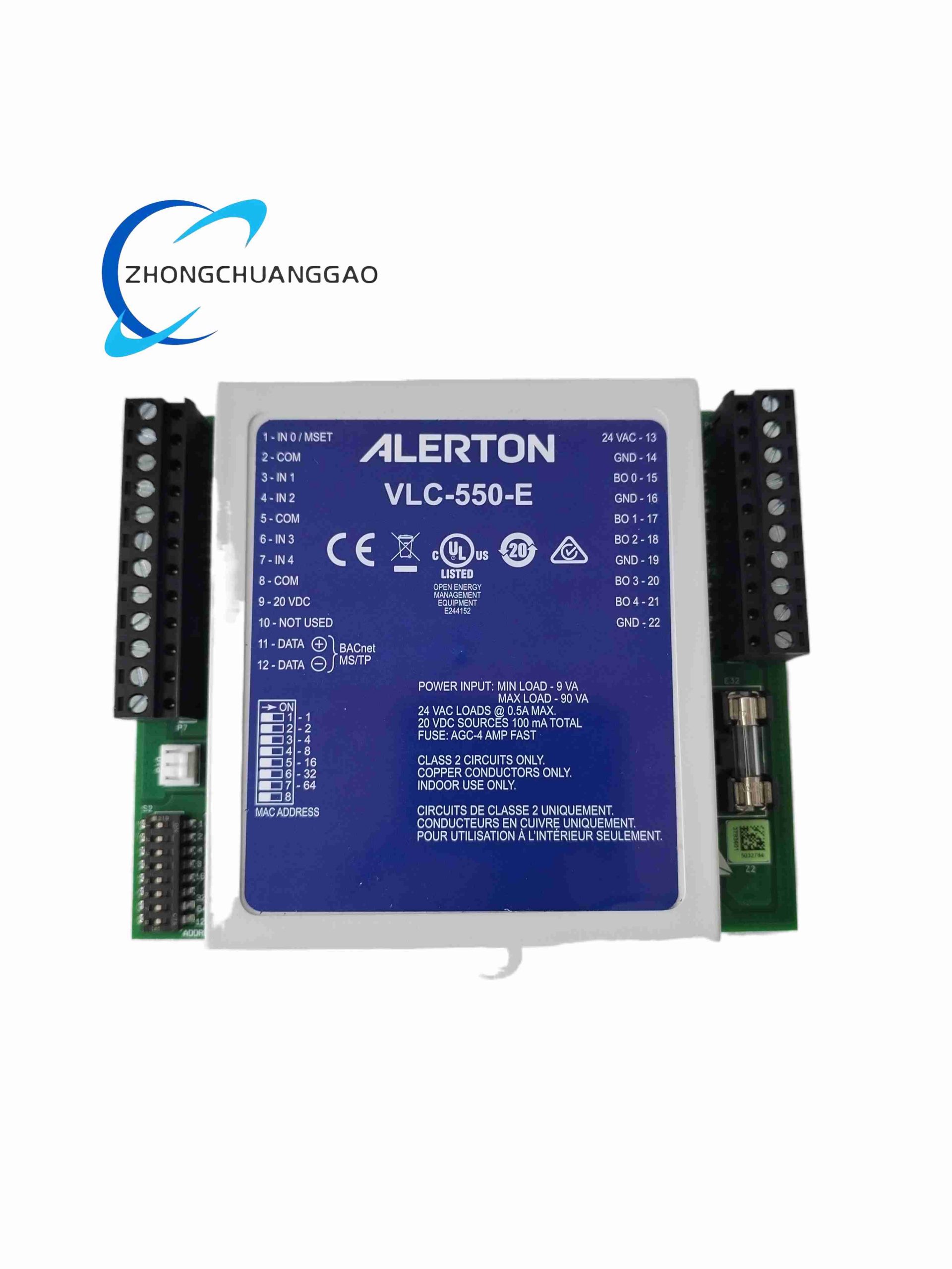
VLC-550-E is a dedicated compact direct digital controller (DDC) independently developed by Honeywell Building Solutions for Variable Air Volume (VAV) terminal box air conditioning control in commercial buildings, office towers, shopping malls and hospital HVAC systems. It integrates analog input, digital input, analog output and relay output channels in one compact DIN rail unit, supporting standalone local control or BACnet IP/MSTP network interconnection with central building management system (BMS).
Description
Core Technical Performance Parameters
- Digital Input Channels: 8 dry contact DI channels for door switches, occupancy sensors, filter differential pressure alarms
- Analog Input Channels: 6 universal AI channels (0–10VDC, 4–20mA, NTC thermistor temperature sensors)
- Analog Output Channels: 4 0–10VDC AO channels for damper actuators, reheat valve modulation
- Relay Digital Output Channels: 6 SPDT potential-free relay outputs rated 24VAC / 3A for fan, heating coil, cooling coil control
- Onboard Communication Interfaces: BACnet MSTP RS485, optional BACnet IP Ethernet module expansion
- Operating Power Supply: 24 VAC (20–30 VAC) HVAC standard transformer power input
- Internal Clock: Built-in real-time clock with 7-day backup lithium battery for schedule retention after power loss
- Control Logic Storage: 128MB flash memory for custom VAV control programs, schedule tables and trend logs
- Operating Ambient Temperature: 0°C to +55°C indoor cabinet operation
- Storage Temperature Range: -30°C to +70°C
- Mounting Standard: 35mm standard DIN rail snap-on mounting
- Physical Dimensions: 185mm width × 110mm height × 62mm depth
- Net Weight: 0.68 kg
- Certifications: CE, UL 916 building automation equipment standard, RoHS compliant
Function Features
- Preloaded factory VAV core control algorithms including space temperature PID regulation, supply air flow tracking, minimum air volume occupancy control and unoccupied setback mode
- E-version exclusive enhanced functions: CO2 air quality concentration linkage ventilation adjustment, multi-speed fan stepped logic, supply air duct frost prevention anti-freeze protection sequence
- Fully programmable via Honeywell building management workstation software; users customize interlock logic, time schedules, alarm thresholds and trending intervals
- BACnet MSTP open standard communication supports seamless data exchange with third-party BMS platforms, no proprietary gateway required
- Built-in historical trending function automatically records space temperature, supply airflow, CO2 concentration and equipment operating state data for energy consumption analysis
- Independent occupancy detection logic switches between comfort occupied temperature setpoint and energy-saving unoccupied setback automatically
- Front panel multi-color LED indicators display power status, network communication activity, channel active state and equipment fault alarms for on-site quick troubleshooting
- Override local manual mode button allows field technicians to manually drive dampers, fans and valves without connecting to central BMS
Working Principle
24VAC standard HVAC power supplies power the entire controller unit. Temperature, airflow, CO2 and occupancy sensor signals are transmitted to universal analog and digital input channels. Onboard 32-bit microcontroller executes preloaded or user-programmed PID and sequential control logic to calculate required damper opening, reheat valve position and fan operating stage. Corresponding control signals are sent to analog output terminals for continuous modulation or relay outputs for staged on-off equipment operation. All real-time operating data is cached in flash memory for trend recording and simultaneously uploaded to central BMS through BACnet MSTP RS485 bus. The integrated real-time clock maintains weekly occupancy schedules and triggers automatic setback energy-saving mode when no occupancy signal is detected. If supply air temperature drops below anti-freeze threshold, the built-in E-series frost protection algorithm activates heating coil relays and fully opens air dampers to eliminate duct icing risk. All input/output channel faults trigger dedicated LED alarm indicators and upload fault codes to the building monitoring system.
Material Composition & Structural Characteristics
- Outer Enclosure: V0 flame-retardant gray ABS plastic DIN rail housing, impact-resistant casing for indoor mechanical room installation
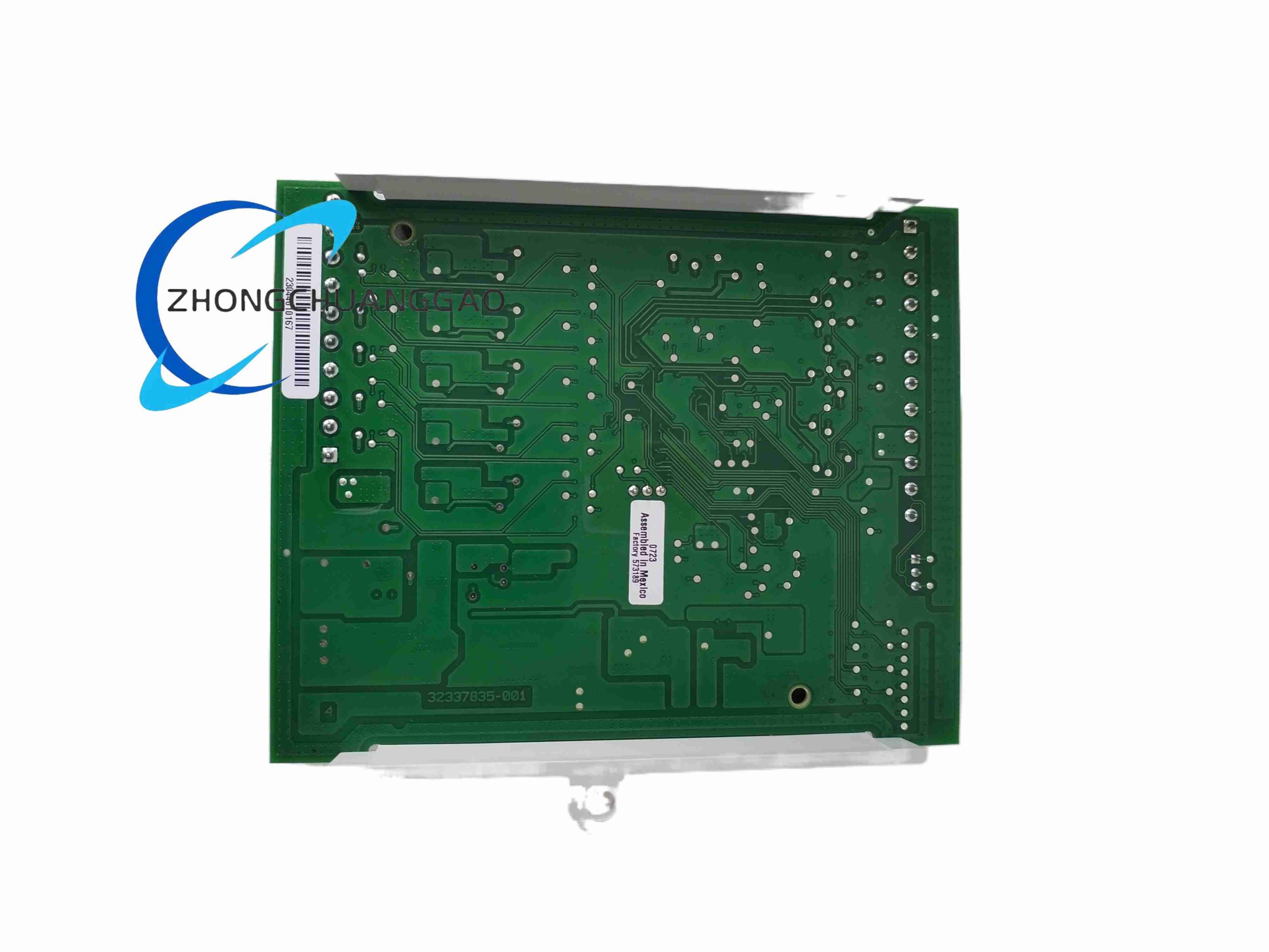
- Main Control PCB: Low-noise multi-layer FR4 circuit board with acrylic conformal coating to resist cabinet humidity and light dust accumulation
- Signal Components: Precision NTC signal conditioning circuits, low-drift PID operational amplifiers, opto-isolators separating field sensors and internal control logic
- Output Relays: Miniature low-power signal SPDT relays with long mechanical service life exceeding 10 million switching cycles
- Wiring Terminals: Cage-clamp spring screw terminals compatible with 0.4–2.5mm² HVAC control wiring
- Communication Interface Hardware: Isolated RS485 transceivers with built-in 120Ω bus termination resistor jumper
Installation Requirements
- Snap horizontally onto standard 35mm top-hat DIN rail inside indoor air handling unit control cabinet; prohibited for outdoor or uninsulated cold mechanical room installation
- Separate low-voltage sensor signal wiring from 220V fan power cables by minimum 20cm distance to avoid control signal interference
- All analog sensor shielded cables use single-point grounding at the controller cabinet earth terminal
- Leave minimum 10mm vertical gap between adjacent VLC-550-E controllers for passive heat dissipation
- Install 24VAC isolation transformer upstream of the controller; do not share transformer power with large inductive loads such as high-power fan motors
Application Scenarios
- Multi-story office building single VAV terminal box temperature and airflow control
- Large shopping mall air conditioning zone independent regulation
- Hospital ward clean room variable air volume ventilation and air quality control
- University classroom energy-saving HVAC schedule automatic management
- Commercial hotel guest room terminal air conditioning monitoring and control
Operation & Maintenance Precautions
- Do not install the unit in locations with water splashing, oil mist or continuous condensation; high humidity causes PCB circuit corrosion and signal drift
- Replace the internal RTC backup lithium battery every 5 years to prevent loss of weekly occupancy schedules during power outages
- Calibrate temperature and CO2 analog input channels once per year to maintain space control precision
- Avoid overloading relay output terminals; do not connect inductive loads above rated 3A without external auxiliary contactors
- Disconnect 24VAC control power supply before modifying sensor or actuator wiring to prevent short-circuit damage to internal signal circuits

Reviews
There are no reviews yet.