
Product Short Description
Product Overview
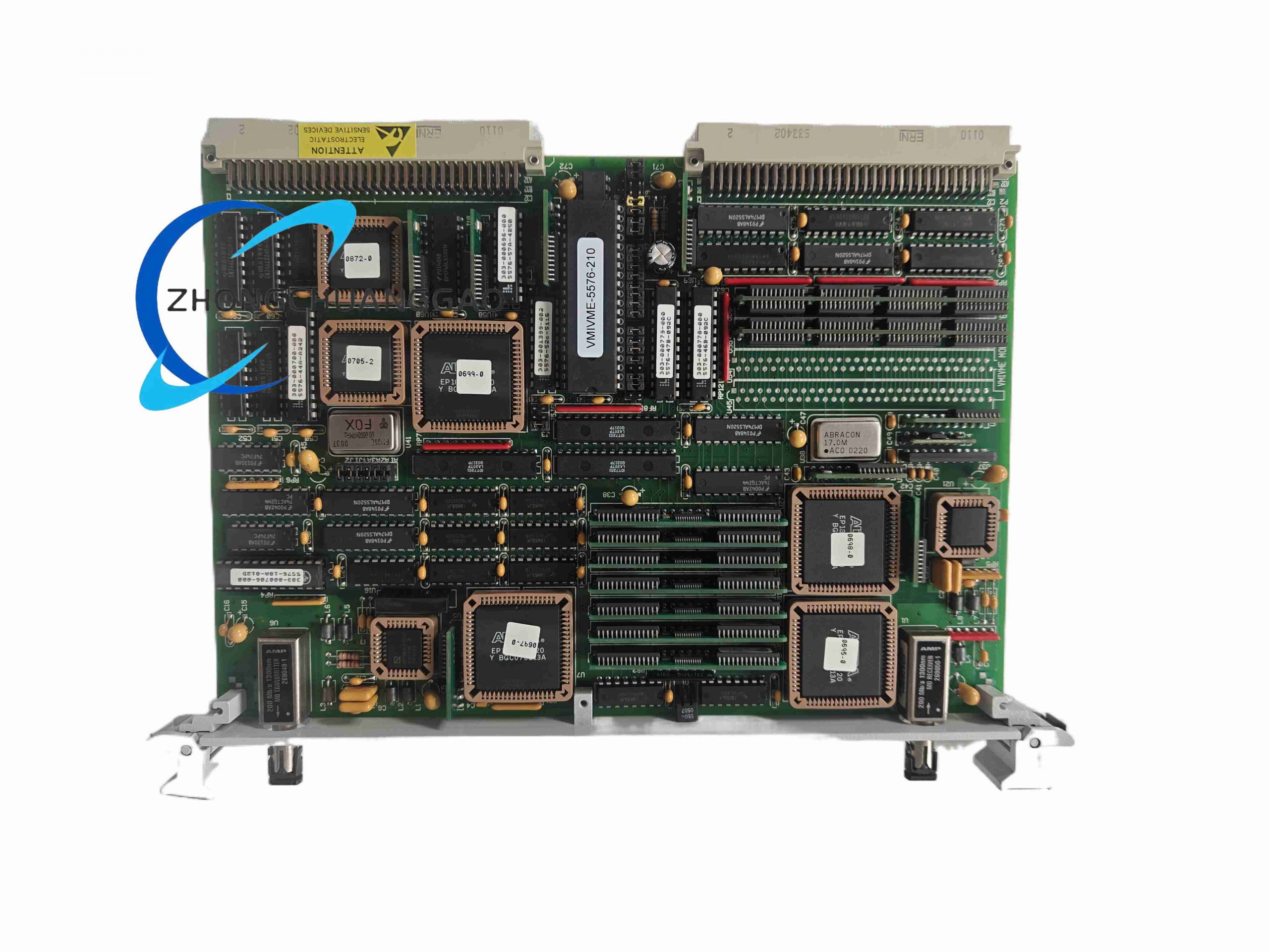
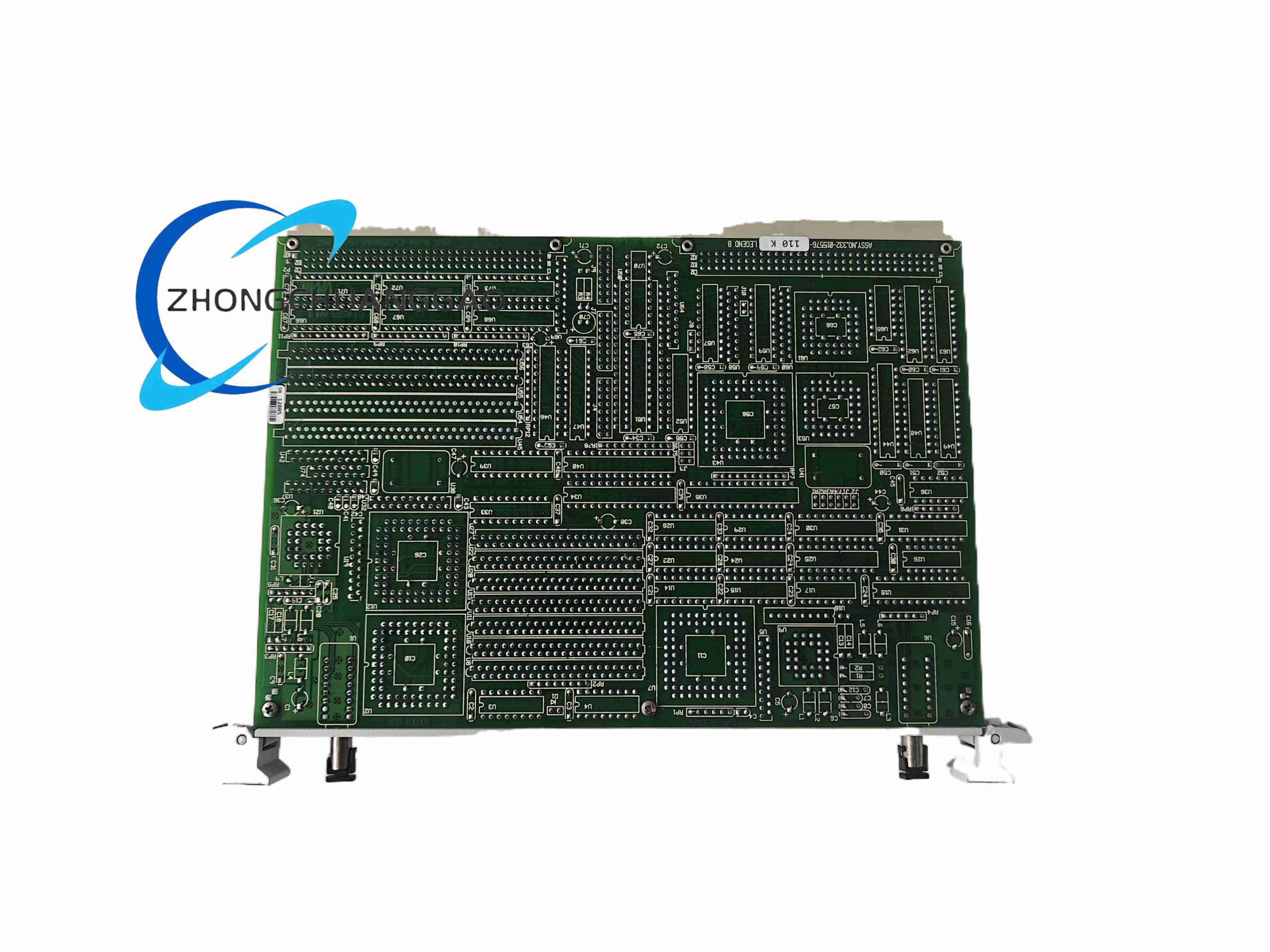
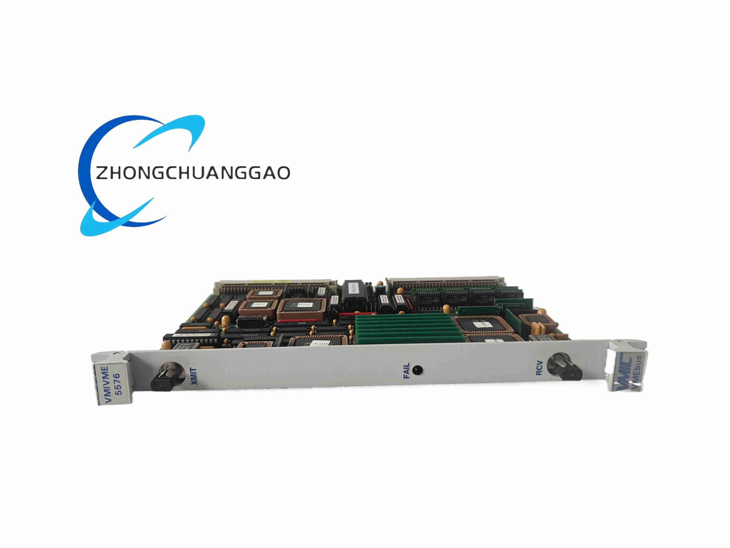
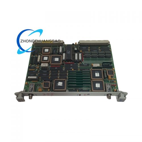
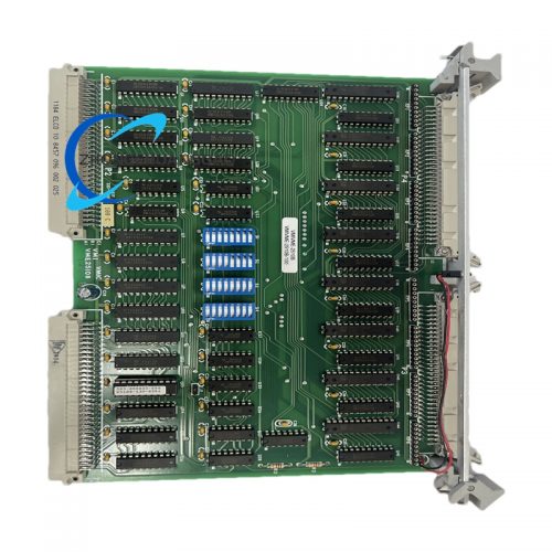
VMIVME-5576-210 is GE Fanuc standard 6U VMEbus industrial analog data acquisition control board, designed for multi-channel high-speed analog signal collection in industrial automation and machinery monitoring VME rack systems. It integrates on-board signal conditioning, multi-channel synchronous ADC conversion and local digital signal processing, compatible with all VME64 standard industrial rack backplanes. Widely used as universal analog acquisition front-end for vibration monitoring, process temperature, pressure multi-parameter measurement in power and heavy manufacturing industries.
Description
Core Technical Specifications
- Bus Standard: VME64 single-height 6U Eurocard VMEbus interface, A16/A24/A32 address space support
- Analog Input Channels: 16 differential fully isolated analog input channels
- ADC Resolution: 16-bit successive approximation analog-to-digital converter per channel
- Max Synchronous Sampling Rate: 100 kSPS aggregate multi-channel sampling speed
- Input Signal Ranges: Software programmable ±10 VDC, ±5 VDC, ±2.5 VDC unipolar/bipolar analog input ranges
- Channel Isolation Voltage: 1500 Vrms galvanic isolation between each analog input channel and VME digital backplane
- Onboard Processing: Local 32-bit RISC microcontroller for real-time signal filtering and engineering unit scaling calculation
- Memory Capacity: 512 KB onboard SRAM temporary waveform data buffer
- Operating Power: 5 VDC, ±12 VDC VME backplane power supply, total power consumption 12 W
- Operating Temperature: 0°C ~ +70°C standard industrial cabinet temperature range
- Form Factor: Single-height 6U VME rack pluggable module, hot-swap optional with compatible VME chassis
- Input Impedance: 10 MΩ high-impedance differential analog input circuit minimizes sensor signal loading error
Functional Features
- 16 fully differential isolated analog input channels eliminate ground loop interference between distributed field sensors and central VME rack
- Software configurable multi-range analog input supports vibration 0~10 VDC signals, 4-20 mA process transmitters with built-in shunt resistor conversion
- Local onboard RISC processor executes real-time digital filtering and linear scaling to convert raw voltage data to engineering units without host CPU resource occupation
- Large 512 KB on-board waveform buffer stores burst transient vibration signals for post-fault event capture
- VME64 high-speed parallel bus data transfer delivers fast measurement data upload to VME rack main CPU controller
- Per-channel overvoltage protection circuit withstands ±15 VDC transient input surge without permanent component damage
- Front-panel screw terminal strip provides convenient field sensor wiring connection without external adapter breakout boards
- Programmable hardware trigger function synchronized with external tachometer speed signals for rotational machine order tracking acquisition
Working Principle
Field analog sensor signals transmit to front-panel differential terminal strip; each channel isolated signal conditioning circuit adjusts signal gain to match programmed input range and suppress common-mode noise. Multi-channel analog multiplexer sequentially routes conditioned analog waveforms to 16-bit ADC converter; digital sampling data transfers to local RISC processor buffer memory. Onboard microcontroller applies digital low-pass filtering and linear engineering unit scaling formulas to raw sample data, then stores processed measurement values to SRAM buffer. VMEbus host CPU accesses buffered data via VME64 parallel bus for system-wide vibration monitoring, alarm logic and data historian recording functions.
Material & Structural Characteristics
- Circuit Board: VME standard 6U multi-layer FR4 PCB with separate analog/digital ground plane isolation
- Isolation Devices: Reinforced insulation optocoupler chips for channel-to-backplane galvanic separation
- Front Panel: Cold-rolled steel with black matte anti-corrosion coating, printed channel numbering and status LED indicators
- Terminal Block: Flame-retardant PA66 plastic, tin-plated copper screw terminals with anti-loose spring washers
- Backplane Connector: Gold-plated VME64 96-pin edge connector, wear-resistant for frequent module plugging
- Analog Circuit Shielding: Mini metal shielding cans cover sensitive low-noise signal circuits to block digital switching EMI
Installation Requirements
- Install the module into a standard 6U single-height VME64 industrial chassis with a compliant active backplane supporting A16/A24/A32 addressing
- Separate analog sensor signal wiring and VME rack power wiring by a minimum of 12 cm inside cable trays to avoid cross interference
- Connect the VME cabinet chassis to a unified plant protective earth grid using a 4 mm² copper braided grounding cable
- Reserve one empty slot between VMIVME-5576-210 and high-power CPU/switching power supply modules for natural heat convection
- All field analog cables must adopt double-shielded twisted-pair structure; ground the outer shield only at the cabinet earth bar
- If the cabinet ambient temperature exceeds 60°C, install auxiliary forced air cooling fans to maintain stable module operation
Application Scenarios
- Thermal power plant VME-based turbine and generator centralized vibration data acquisition systems
- Heavy metallurgy rolling mill multi-point vibration, pressure and temperature synchronous measurement racks
- Nuclear power plant auxiliary rotating equipment multi-parameter analog signal collection units
- Marine vessel engine room machinery condition monitoring VME control cabinets
- Aerospace test bench rotating component high-speed transient vibration capture equipment
- Petrochemical plant distributed compressor multi-channel process signal acquisition systems
Operation & Maintenance Precautions
- Do not apply input voltage exceeding ±15 VDC to any analog channel; sustained overvoltage will burn out internal signal conditioning amplifiers
- Conduct annual inspection of terminal screw tightness; thermal cycling in industrial environments loosens wiring and introduces measurement drift
- Avoid routing analog cables parallel with frequency converters, welding machines and high-current contactors
- Regularly clean the front panel terminal block to remove oil mist, metal dust and corrosive chemical residues every 6 months
- The onboard SRAM buffer data will be cleared after rack power loss; back up critical transient waveform data to external storage in advance
- Calibrate channel linearity and isolation performance every 2 years with standard DC signal calibrators per IEEE 1057 measurement standards
Reviews
There are no reviews yet.