
Product Short Description
Product Overview
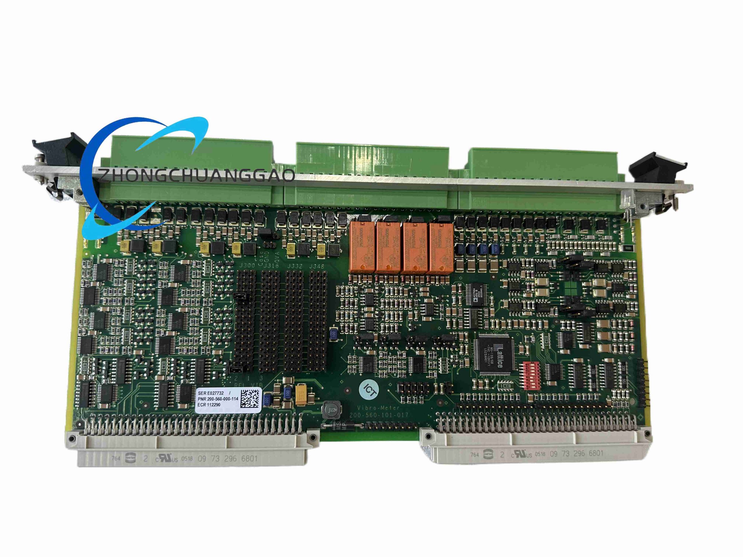
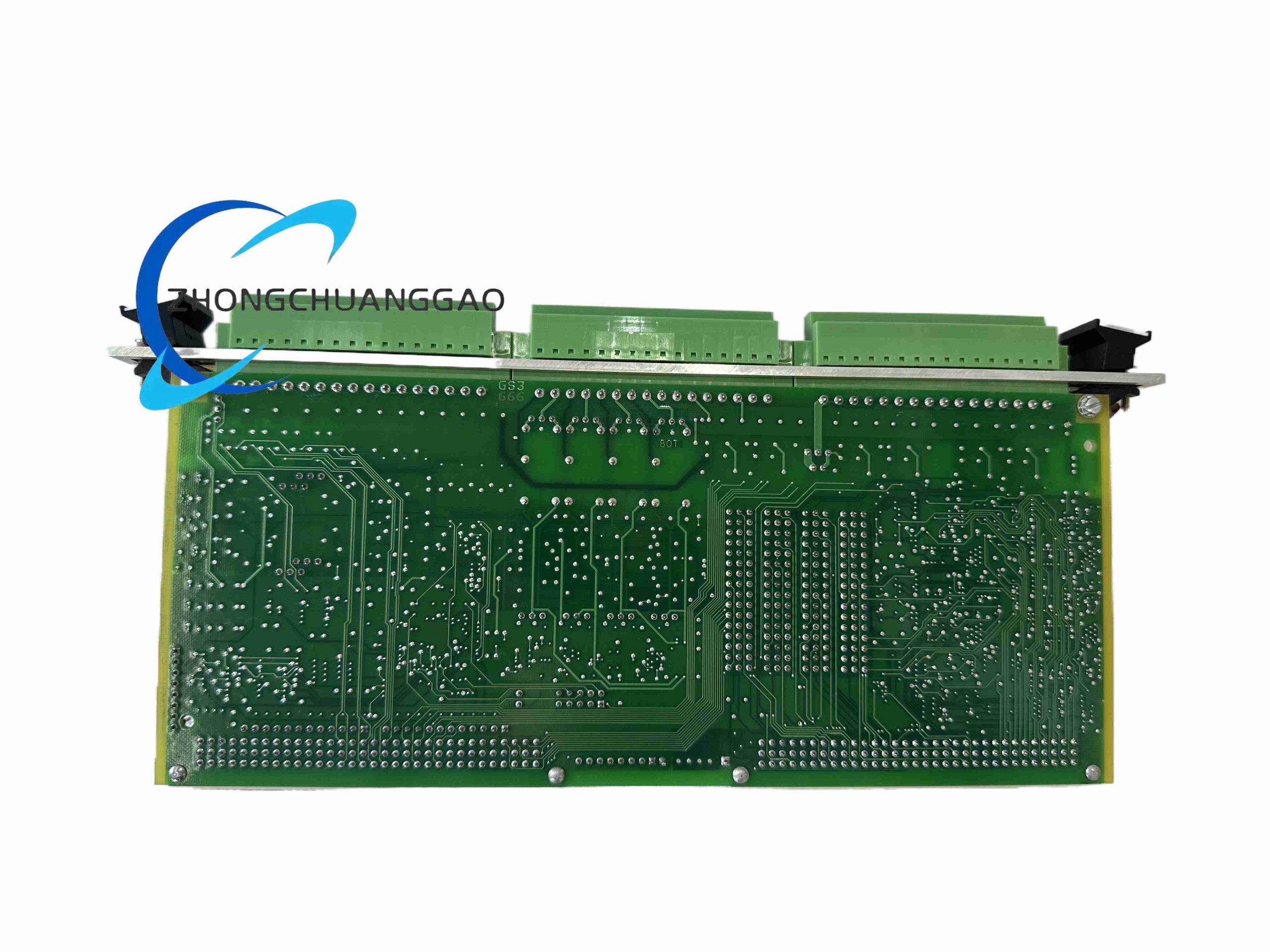
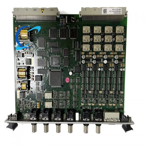
VMF-IOC4T is paired slave I/O interface card matched with VMF-MPC4 main processing card in Meggitt Vibro-Meter VMF modular machinery protection system. Two model variants: 200-560-000-111 standard industrial general configuration; 200560-101-017 enhanced high-fidelity version with extended dynamic range and advanced multi-stage noise filtering circuit. The card acts as physical wiring interface connecting all field vibration, displacement, temperature sensors to MPC4 DSP processing core, integrating on-board signal conditioning, sensor excitation and isolated analog re-output functions.
Description
Core Technical Specifications
- Independent Input Channels: 4 fully galvanic isolated dynamic signal input channels
- Supported Sensor Types: IEPE piezoelectric accelerometer, moving-coil velocity transducer, eddy current proximity probe, 4-20 mA temperature transmitters
- ADC Sampling Resolution: 24-bit per channel synchronous analog-to-digital conversion
- Max Synchronous Sampling Rate: 102.4 kHz multi-channel simultaneous acquisition
- Dynamic Signal Range: 120 dB ultra-wide range (0.01 g low vibration ~10 g high impact vibration)
- Channel Isolation Rating: 2500 Vrms optoelectronic isolation between individual channels
- Analog Re-Output: 4 isolated 0~10 VDC buffered raw signal output channels for external DCS acquisition
- Sensor Excitation Supply: Programmable constant current 2 mA IEPE power, -24 VDC eddy probe excitation
- Backplane Communication: VMF high-speed industrial packet bus bidirectional data exchange with MPC4 main card
- Operating Environment: -40°C ~ +85°C cabinet temperature, 5%~95% RH non-condensing
- Form Factor: 6U Eurocard rack pluggable module, hot-swap compatible
- Signal-to-Noise Ratio: ≥90 dB after dual hardware/software noise reduction filtering (200560-101-017 enhanced model)
Functional Features
- Four fully isolated input channels eliminate cross-channel signal crosstalk even under strong industrial electromagnetic interference environments
- Automatic sensor type identification circuit matches excitation voltage/current parameters without manual hardware jumper adjustment
- Enhanced variant (200560-101-017) adopts three-stage analog filtering to suppress 50/60 Hz power frequency interference from factory power grids
- Synchronous high-speed multi-channel sampling meets ISO 10816 rotating machinery vibration measurement precision standards
- Onboard overvoltage, overcurrent and electrostatic discharge protection on all field input terminals to prevent lightning surge damage
- Buffered isolated analog re-output terminals allow raw vibration signal transmission to third-party data historians without signal attenuation
- Hot-swap module design permits maintenance replacement without system rack power shutdown
- Screw-locking heavy-duty terminal strip supports thick industrial multi-core shielded field wiring up to 2.5 mm² cross-section
Working Principle
Field sensor analog signals transmit via shielded cables to VMF-IOC4T rear terminal strip. Per-channel isolated signal conditioning circuit provides matched sensor excitation power, filters out industrial EMI noise and amplifies weak vibration signals to standardized voltage levels. 24-bit synchronous ADC converts analog waveform to digital data stream, which transmits to paired VMF-MPC4 processing card through rack backplane bus for DSP vibration calculation and fault threshold comparison. Simultaneously, buffered isolated DAC circuit reproduces filtered raw vibration signal as 0~10 VDC analog output for external plant control system acquisition.
Material & Structural Characteristics
- Main Circuit PCB: Multi-layer industrial high-Tg FR4 board with full-channel ground isolation layout
- Terminal Block Assembly: PA66 flame retardant plastic, copper alloy spring anti-loose screw terminals
- Isolation Components: High-voltage optocoupler chips with reinforced insulation encapsulation
- Front Panel: Matte black aluminum alloy with channel status LED indicator array
- Backplane Connector: Gold-plated multi-pin Eurocard edge connector with vibration-resistant spring contacts
- Internal Shielding: Miniature metal shielding cans covering analog signal circuits to block high-frequency EMI interference
Installation Requirements
- Physically pair each VMF-IOC4T card with one VMF-MPC4 processing card in adjacent rack slots; backplane interlock connectors must fully engage
- Separate field sensor signal wiring from high-power AC motor control cables with minimum 15 cm vertical spacing inside cable trays
- All shielded sensor cable outer braid shield single-end grounded to VMF rack chassis earth bar; field sensor side shield floating
- Install rack inside ventilated industrial control cabinet; add auxiliary cabinet cooling fan if continuous ambient temperature exceeds 70°C
- Torque terminal block screws to factory specified 0.8 N·m tightening torque to prevent wiring thermal loosening
- Reserve one empty rack slot between IOC4T terminal cards and rack power supply modules for heat dissipation
Application Scenarios
- Large gas/steam turbine centralized vibration protection monitoring systems in power generation plants
- Petrochemical complex multi-bearing centrifugal compressor full-condition monitoring rack systems
- Wind turbine farm gearbox and generator vibration centralized data acquisition
- Nuclear power station auxiliary rotating machinery multi-point vibration measurement
- Offshore oil platform gas compressor machinery protection front-end signal conditioning rack
Operation & Maintenance Precautions
- Do not hot-swap module during peak vibration measurement sampling cycles; temporary data loss will occur during bus reconnection
- Conduct quarterly visual inspection of terminal block wiring for oil contamination or corrosion in process plant environments
- Enhanced 200560-101-017 variant requires annual filter circuit performance bench calibration to maintain 90 dB SNR rating
- Avoid routing sensor cables parallel with welding equipment and high-frequency inverter power lines to eliminate signal noise
- All unused input channels must be terminated with factory-supplied 50 Ω matching resistors to prevent stray signal interference
- Replace module immediately if front-panel channel fault LED remains illuminated after complete sensor and cable troubleshooting
Reviews
There are no reviews yet.