
Product Short Description
Product Introduction
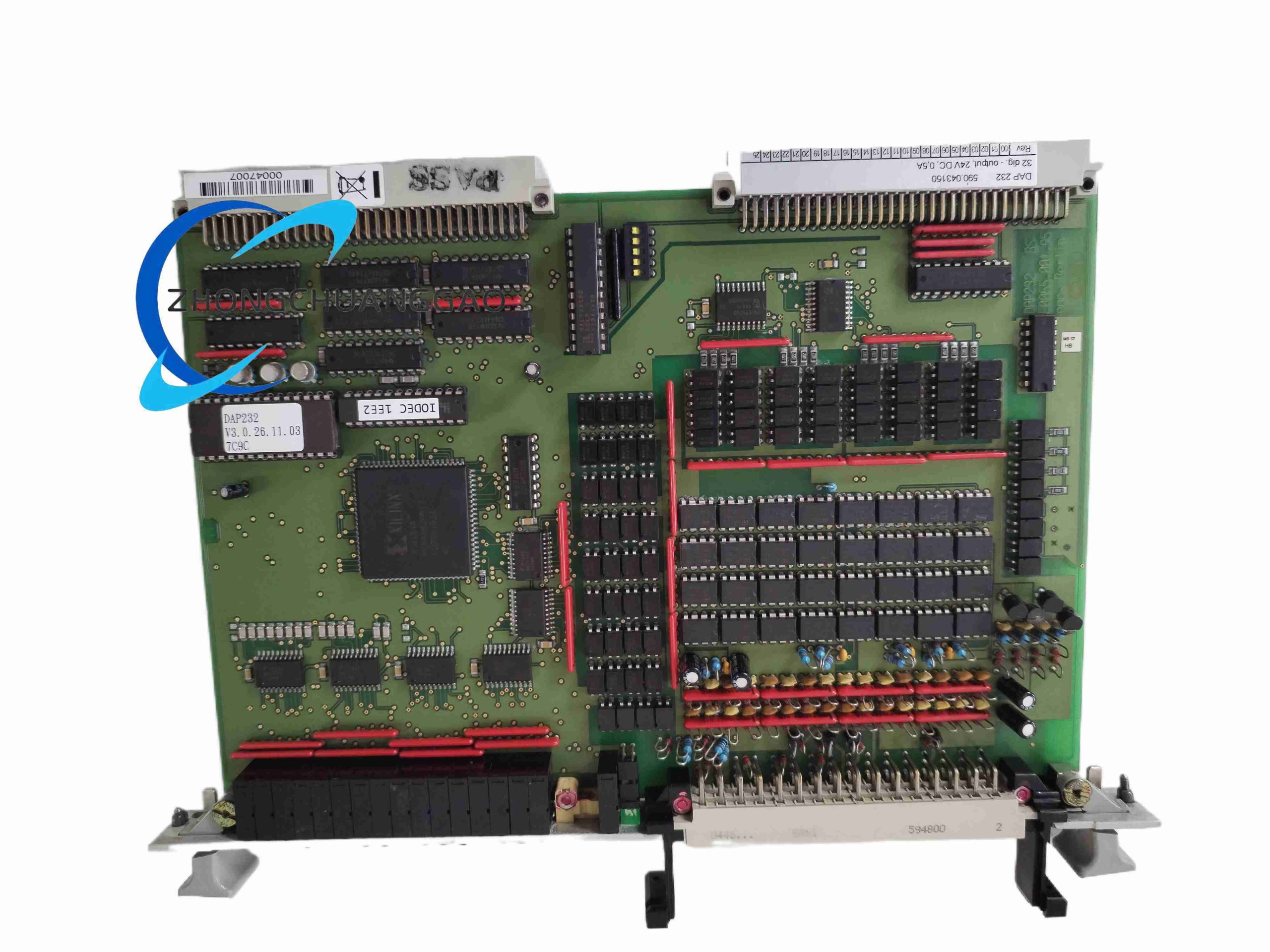
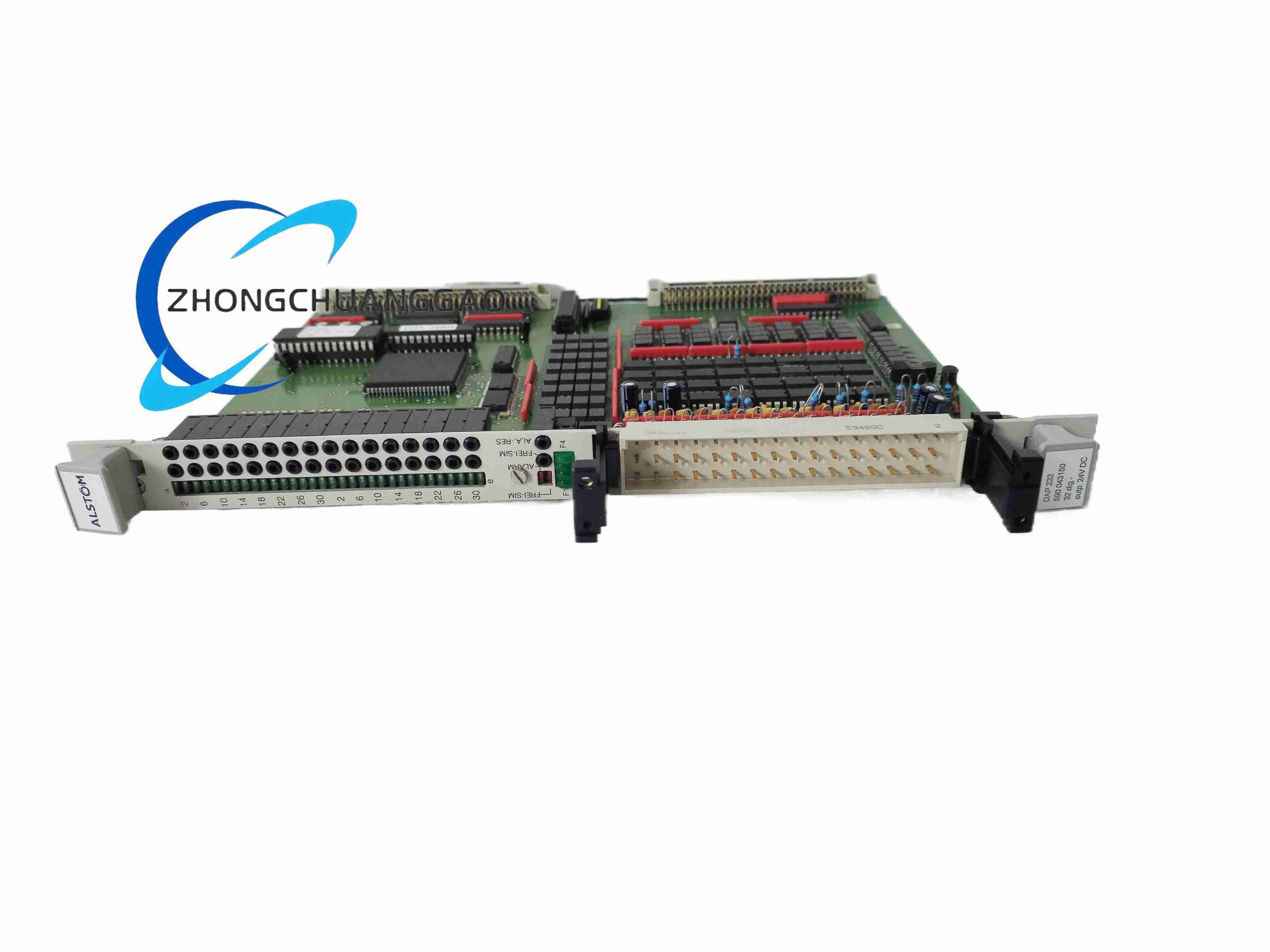
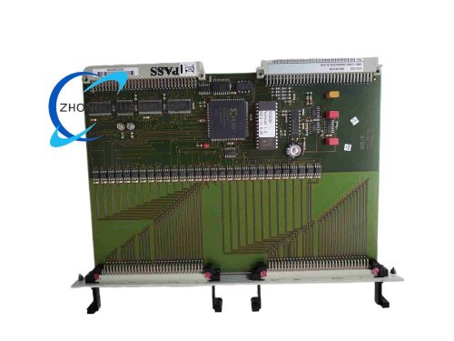
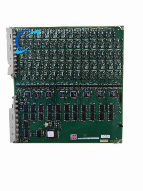
Custom industrial printed circuit board assembly for large synchronous generator static excitation control system, amplifies low-level pulse trigger signals from main excitation controller to drive high-power IGBT thyristor rectifier bridges in thermal power, hydroelectric power station excitation cabinets. 590.043150 denotes factory drawing part number matching DAP232 base model.
Description
Technical Specifications
- Input Pulse Signal Level: 0–5V DC logic pulse input
- Output Drive Current: 1.2A peak gate drive output per channel
- Channel Count: 6 independent pulse amplification channels for 6-pulse rectifier topology
- Working Power Supply: ±15V DC isolated auxiliary power
- Insulation Withstand Voltage: 4000V AC between control logic side and power drive side
- Operating Temperature Band: -10°C ~ +70°C
- Pulse Frequency Range: 50Hz ~ 400Hz synchronous trigger pulse
Functional Features
- High-speed pulse edge shaping circuit eliminates trigger signal distortion over long cabinet wiring
- Per-channel over-current short-circuit protection for thyristor gate drive circuit
- Pulse loss detection logic triggers excitation system alarm relay contact output
- Temperature monitoring NTC thermistor integrated for overheating protection
- Plug-in edge connector design for rapid on-site board replacement during power unit maintenance
Performance Parameters
- Pulse Rise Time: ≤200ns amplified output edge speed
- Channel Phase Matching Error: ≤0.5 electrical degree across six output channels
- Maximum Continuous Operating Vibration: 10–1500Hz, 1g sine vibration
- Service Design Life: 150,000 hours continuous operation
Material Composition
High thermal conductivity FR-4 PCB with thick copper trace layers, silicon high-speed power drive transistors, epoxy encapsulated isolation transformers, metal oxide varistor surge protection components
Structural Characteristics
Standard 6U Eurocard PCB dimension, front panel with status LED indicators and fault alarm terminal strip, rear gold-plated edge connector for rack bus power and signal connection
Working Principle
Low-amplitude phase trigger pulses transmitted from excitation regulator CPU board enter input buffer circuit, isolated via high-frequency pulse transformer, amplified by power transistor stage to generate high-current gate drive pulses for rectifier thyristor modules. Onboard monitoring circuit continuously verifies pulse presence and drive loop integrity to trigger plant control system alarm upon failure.
Advantage Highlights
- Precise multi-channel phase matching ensures balanced rectifier bridge current output
- Full galvanic isolation separates low-voltage control logic from high-voltage power circuit
- Wide frequency compatibility adapts to hydro variable-speed generator excitation systems
- Standard Eurocard form factor interchangeable across Alstom DAP excitation rack series
Applicable Industries
Thermal power generation plant, hydroelectric power station, pumped storage power plant, industrial synchronous motor large excitation control
Installation Requirements
- Install inside forced-air cooled excitation control cabinet with cross-flow ventilation fan
- Maintain minimum 30mm vertical clearance above and below PCB assembly
- Separate low-voltage control wiring and high-power thyristor wiring into dedicated cable ducts
- Cabinet grounding bus bonded to power station main equipotential grounding grid
Usage Precautions
- Power off entire excitation cabinet rack before removing DAP232 PCB assembly
- Avoid physical scratch damage to rear gold-plated edge contact pins
- Clean PCB surface dust accumulation with dry compressed air every 6 months
- Replace unit immediately upon persistent pulse loss alarm to prevent generator excitation imbalance
Reviews
There are no reviews yet.