
Product Short Description
Product Brief
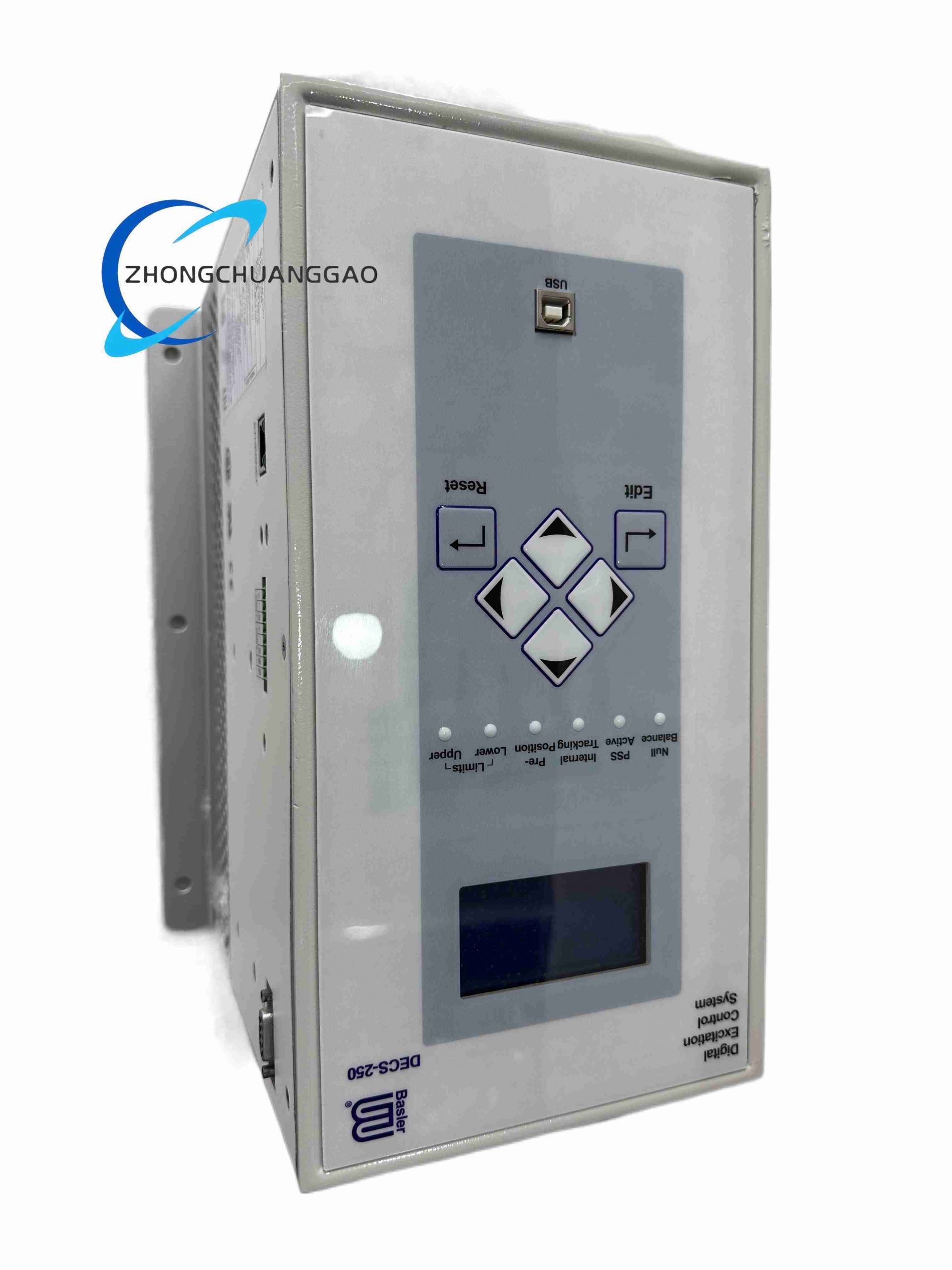
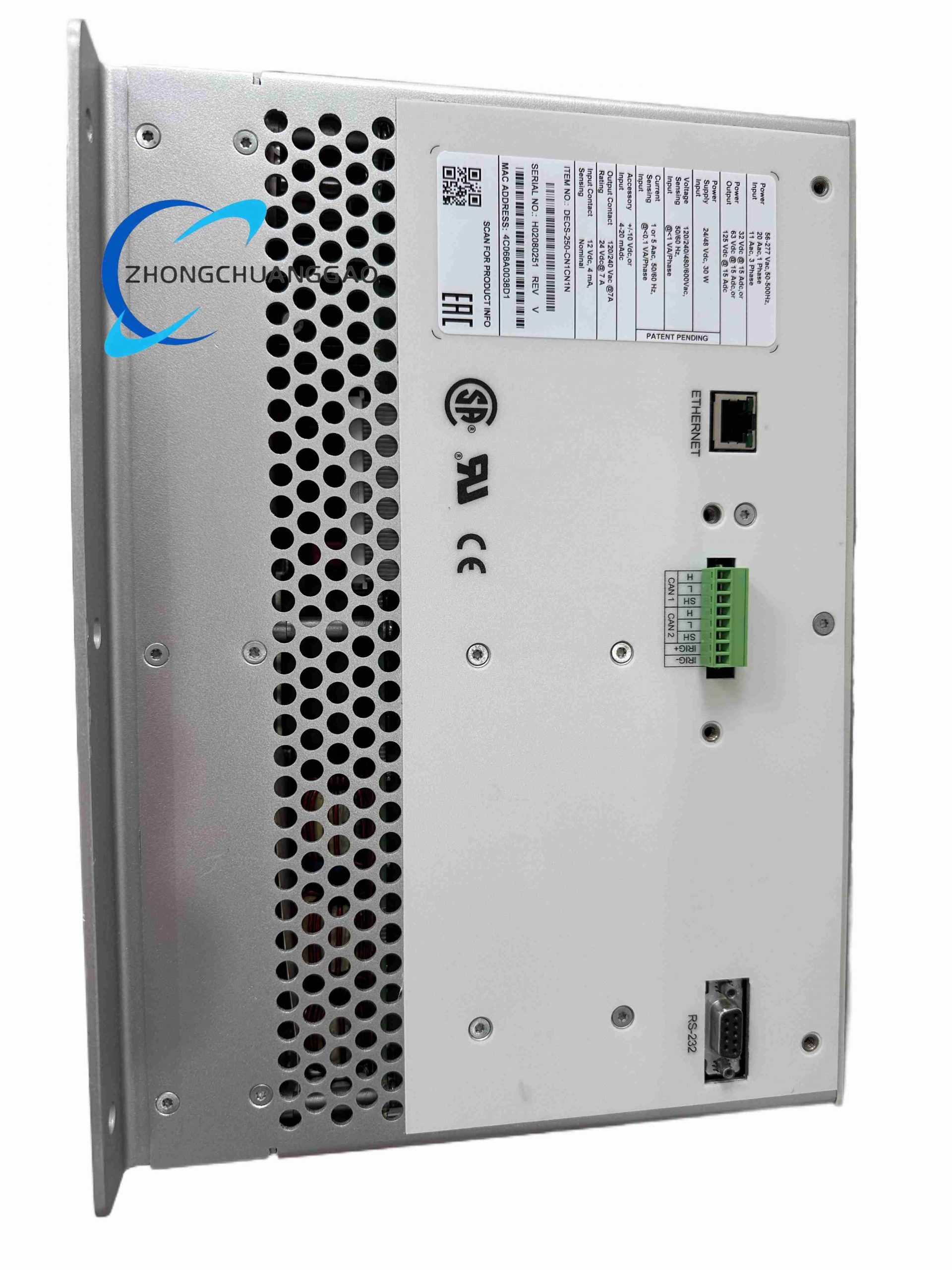
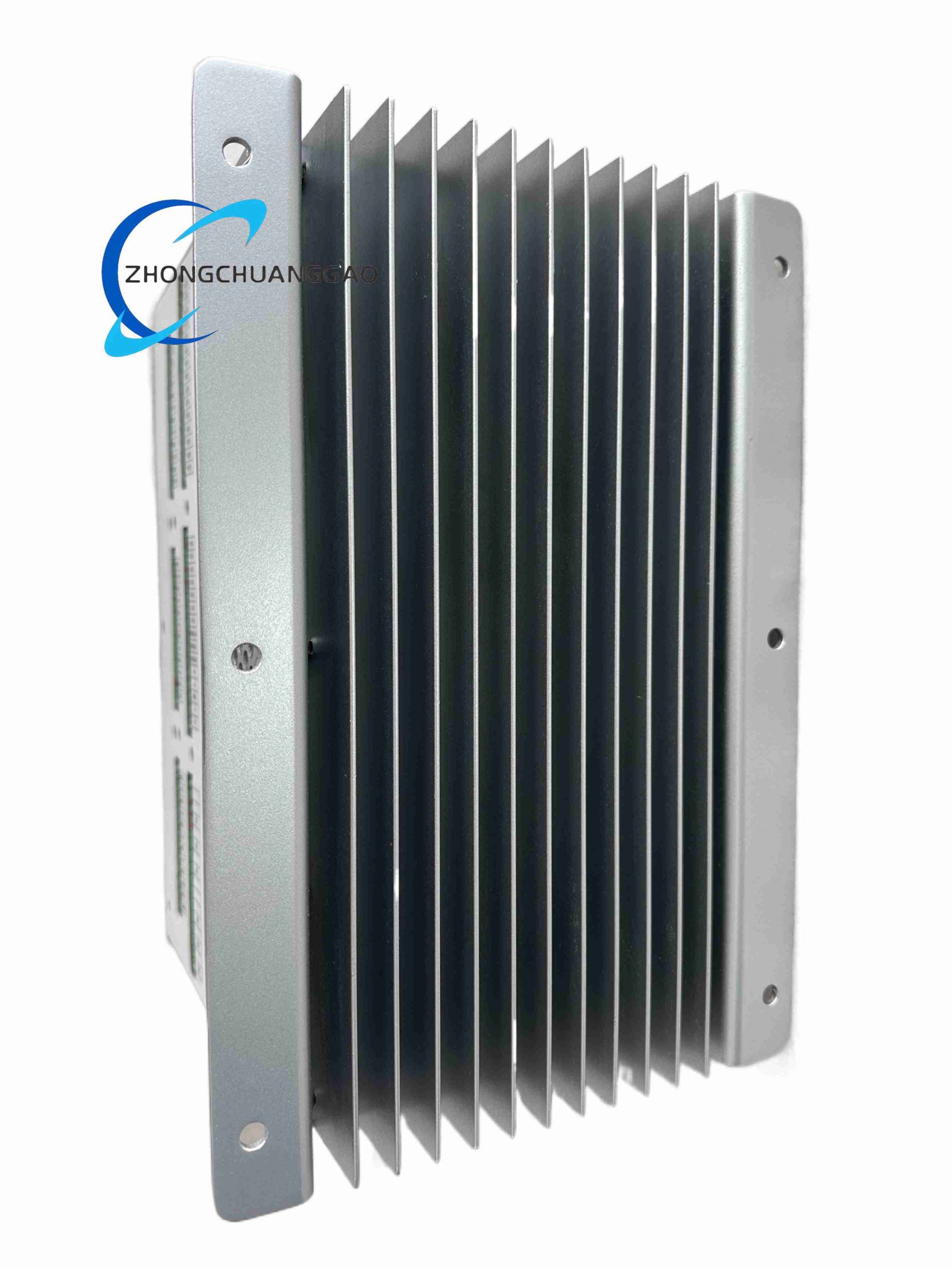
Description
Model Series Definition
- DECS: Digital Excitation Control System series
- 250: Third-generation high-power universal excitation regulator hardware platform
- CN1: Single negative forcing bidirectional excitation control channel configuration
- CN1CN1: Two identical independent negative forcing redundant master/backup channels
- N: Extended industrial communication interface version (Ethernet TCP/IP + Modbus TCP + IEC 60870-5-104 built-in)
Technical & Performance Parameters
- Redundant Channel Core Specifications
- Quantity of Independent Isolated Control Channels: 2 master/backup negative forcing bidirectional excitation channels
- Bumpless Channel Automatic Switching Transfer Time: < 8 ms
- Cross-Channel Real-Time Mutual Fault Monitoring Cycle: 0.5 ms
- Separate Independent Auxiliary Power Input for Each Channel, No Shared Power Circuit
- Bidirectional Excitation Power Output Specs
- Configurable Positive Excitation DC Voltage Ranges: 63 VDC / 125 VDC / 250 VDC
- Matching Negative Forcing Demagnetization DC Voltage Ranges: Same as positive voltage rated value
- Continuous Steady-State Positive Excitation Current per Channel: 25 ADC
- Peak Transient Negative Demagnetization Current per Channel: 32 ADC, maximum allowable continuous duration 8 seconds
- Full-wave six-thyristor bidirectional rectifier bridge per single channel
- Voltage Regulation & Dynamic Performance
- Steady-State Terminal Voltage Regulation Accuracy: ±0.15%, exceeding ISO 8528-5 standard requirements
- Post-fault Generator Terminal Voltage Recovery Time: ≤ 60 ms under grid short-circuit transient disturbance
- Power Factor Control Adjustable Range: 0.6 lagging to 0.6 leading full coverage
- Reactive Power Droop Adjustment Range: 0% – 10% linear configurable
- Sensing & Auxiliary Power Electrical Specs
- Generator Terminal Voltage Sensing Input: Auto-adaptive 120 VAC / 240 VAC / 480 VAC / 690 VAC, 50 / 60 Hz / variable frequency generator compatible
- Single-channel auxiliary control power input: 85 – 277 VAC single-phase, 60 VA rated power consumption
- Protection & Data Storage Specs
- Full redundant duplicated protection logic on both channels: field overcurrent, negative field overcurrent, U/F overexcitation, stator current limiting, under-excitation loss of field, overvoltage, undervoltage
- SER Sequence Event Recorder Storage Capacity: 256 independent fault records per channel, time stamp precision 1 ms
- Transient Oscillography Storage: 16 groups of COMTRADE standard waveform files, up to 12 analog monitoring variables per waveform record
- Multi-Channel Communication Interfaces
- Wired Serial Interfaces: Dual isolated RS485 Modbus RTU
- Ethernet Industrial Communication: Dual redundant Ethernet ports, Modbus TCP, IEC 60870-5-104, IEC 61850 MMS optional protocol stack
- Local Configuration Port: USB 2.0 front panel service port for BESTCOMS™ Plus software connection
- Environmental Operating Parameters
- Continuous Operating Ambient Temperature: -10°C to +70°C
- Storage Temperature Range: -45°C to +85°C
- Operating Relative Humidity: 5% – 95% non-condensing
- Vibration Compliance Standard: IEC 60068-2-6, 10–150 Hz, 1 mm amplitude continuous vibration tolerance
- Ingress Protection Class: IP20, only for indoor control cabinet installation
- Mechanical Dimension & Weight
- Overall Outer Size (Width × Height × Depth): 483 mm × 133 mm × 380 mm (standard 19-inch rack, 3U height dual-channel unit)
- Net Unit Weight: 14.7 kg
Material Composition
- Outer Chassis: Reinforced thick-gauge cold-rolled steel shell with anti-rust epoxy powder coating, dual independent compartment isolation structure separating channel A and channel B power circuits
- Power Stage Components: High-current fast-switching industrial thyristor modules with high reverse withstand voltage, low thermal resistance packaging
- Heat Dissipation System: Two sets of large-volume extruded aluminum fin heat sinks, each channel equipped with independent temperature-controlled variable-speed cooling fan
- Control Circuit Board: Multi-layer gold-plated industrial FR4 PCB with ESD shielding copper foil layer, dual independent DSP main control boards for master and backup channels
- Signal Isolation Components: High-voltage optocouplers and isolation transformers for complete separation of power circuit and low-voltage sampling signal circuits
- Terminal Hardware: Nickel-plated copper high-current screw terminals for excitation power output; spring-cage gold-plated signal terminals for sensing and communication wiring
- Front Panel Assembly: Impact-resistant scratch-proof polycarbonate LCD protective cover, wear-resistant silicone physical operation buttons
Structural Features
- Standard 3U 19-inch rackmount double-compartment split housing, physical metal partition completely isolates Channel A and Channel B hardware circuits to eliminate cross-channel electrical interference
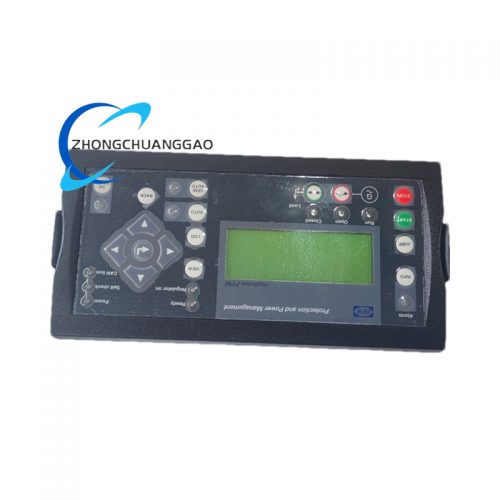
- Dual independent front human-machine operation areas: Separate LCD display, status LED indicators, parameter adjustment buttons for master channel and backup channel
- Rear panel partitioned terminal layout: Independent terminal blocks for Channel A sensing, power supply, excitation output; separated terminal blocks for Channel B corresponding circuits; centralized communication port terminal area at bottom rear
- Built-in internal cross-channel fault detection bus, no external wiring required for master-backup status real-time exchange
- Front panel embedded USB service port for on-site parameter download/upload without cabinet rear wiring disassembly
- Front panel multi-color LED status indicator group: Power normal green, excitation running blue, channel fault red, negative forcing activation amber, communication link white
- Built-in overheat mechanical temperature cut-off switch for each heat sink assembly, secondary hardware protection independent of software logic
Working Principle
When generator terminal voltage deviates from user-set reference value:
- Voltage sag condition: Positive thyristor bridge outputs forward DC excitation current to rotor winding to boost magnetic flux and lift terminal voltage rapidly
- Voltage surge / grid fault transient condition: Negative forcing thyristor bridge outputs reverse demagnetization current to rotor winding, quickly eliminate excess magnetic flux and suppress overvoltage within 60 ms
Cross-channel monitoring bus continuously compares operation data, excitation current output status and hardware health signals of two channels. Once master channel hardware failure, power stage overheating or signal loss is detected, bumpless transfer logic cuts master channel output within 8 ms and switches all excitation control authority to backup channel; generator terminal voltage maintains stable output without fluctuation during switching process.
All operating parameters, fault events and transient waveform data are stored in non-volatile flash memory of each channel independently; data can be uploaded to upper SCADA power monitoring system via dual redundant Ethernet communication ports.
Core Function Features
- Dual redundant full negative forcing bidirectional excitation topology, 8 ms ultra-fast bumpless master-backup automatic transfer, zero power generation interruption
- ±0.15% ultra-high steady-state voltage regulation precision, meets strict grid-connected power unit technical access standards
- Independent bidirectional current limiting hardware protection for each channel, separate threshold configuration for positive excitation and negative demagnetization current
- Built-in complete redundant protection suite: loss of field protection, U/F ratio overexcitation protection, stator dual-stage current limiting, over/under terminal voltage alarm and trip
- Native integrated PSS2A power system stabilizer algorithm to suppress low-frequency oscillation of large grid-connected synchronous generators
- Dual redundant Ethernet communication with multi-standard protocol stack, supports remote centralized monitoring, parameter modification and fault data retrieval
- Massive capacity SER event recorder and COMTRADE oscillography storage for post-fault power system accident analysis
- Independent offline maintenance mode for single channel: one channel can be powered off for inspection, calibration or component replacement while the other channel sustains full generator excitation operation
- Multi-set parameter group storage, supports one-click switching of working parameters for grid-connected / island / standby generator operation modes
- Adjustable reactive power droop function for parallel operation of multiple synchronous generator units on the same busbar
Advantage Highlights
- Dual physically isolated redundant negative forcing architecture eliminates all single-point failure risks of excitation system, applicable to zero-outage critical power supply scenarios
- 60 ms ultra-fast negative demagnetization voltage recovery performance significantly improves generator transient stability under grid short-circuit and voltage surge faults
- ±0.15% regulation accuracy is superior to general single-channel excitation regulators, satisfies strict power grid grid-connection assessment requirements
- Dual redundant Ethernet communication ports avoid single communication cable breakage leading to remote monitoring signal loss
- Independent variable-speed cooling fan for each channel heat sink reduces average fan wear rate and extends overall unit service life
- Offline single-channel maintenance function eliminates generator shutdown demand during routine excitation system overhaul, greatly improving power station operation efficiency
- Unified BESTCOMS™ Plus configuration software compatible with full Basler DECS series, low learning cost for maintenance technicians
- 25 ADC continuous positive excitation current capacity adapts to large-capacity generators with heavy rotor winding load
Applicable Industries
Installation Requirements
- Install on standard 19-inch industrial generator control rack, reserve minimum 150 mm rear depth ventilation space for dual heat sink assemblies
- Channel A and Channel B auxiliary AC power supply must be derived from two completely independent upstream power circuits to avoid simultaneous power loss of both channels
- Excitation output high-current cables for two channels adopt shielded high-temperature copper wire with minimum cross-section 10 mm²; cable length and wiring impedance of master and backup channels must be consistent
- Generator voltage sensing signal twisted shielded cables shall be laid in separate wiring ducts, maintain minimum 20 cm separation distance from high-current excitation power cables
- Dual Ethernet communication cables use CAT6A shielded network wire, both cable shielding layers single-point grounded at central monitoring cabinet
- For continuous full-load operation under ambient temperature above 50°C, install cabinet forced ventilation fan with minimum air flow rate 120 CFM
- All high-current terminal screws must be tightened to torque value 2.2 N·m to prevent thermal accumulation under long-term bidirectional current load
Operation & Maintenance Precautions
- Forbid long-term continuous negative demagnetization operation exceeding rated 8 seconds peak duration; over-limit operation will trigger thyristor thermal lockout protection
- Execute monthly automatic channel transfer test to verify bumpless switching function and cross-channel fault detection logic integrity
- Clean dual aluminum heat sink fin dust and fan filter mesh every 3 months for power station environments with coal dust or water vapor
- Complete full calibration of positive/negative excitation current and voltage sensing channels every 24 months via BESTCOMS™ Plus software to guarantee regulation precision
- Never disconnect both channel auxiliary power supplies simultaneously while generator is in running state, which will lead to complete loss of excitation and generator voltage collapse
- Replace cooling fans immediately once abnormal noise or speed drop is detected; fan failure will cause heat sink overheating and excitation current limiting derating
- Do not modify factory default negative field overcurrent protection threshold without professional power system engineering calculation; improper parameter setting may cause permanent damage to generator rotor winding insulation
- Backup channel cannot be removed or powered off for more than 72 consecutive hours; long-term single-channel operation will accelerate power stage component aging due to uneven load wear
Reviews
There are no reviews yet.