
Description
Technical Specifications
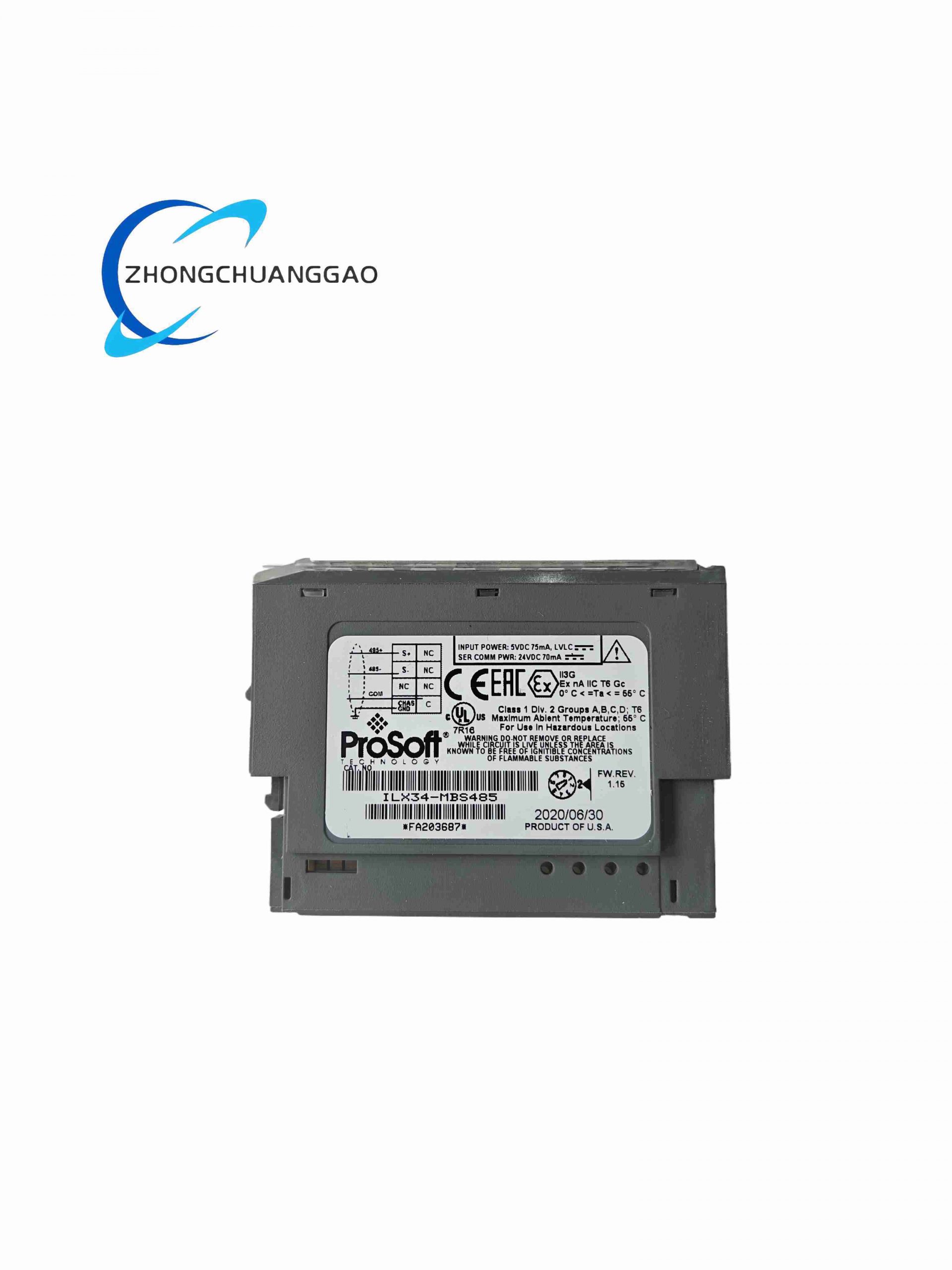
- PLC Backplane Compatibility: Allen‑Bradley CompactLogix 5370 / 5480 series control racks
- Serial Interface Standard: RS485 2-wire half-duplex Modbus RTU electrical layer
- Communication Mode Selectable: Modbus Master Mode / Modbus Slave Mode software configurable
- Supported Modbus Function Codes: 01,02,03,04,05,06,15,16 full standard Modbus function set
- Max Serial Baud Rate: 115200bps
- Backplane Data Exchange: Implicit and explicit messaging to CompactLogix controller tag memory
Functional Features
- Dual configurable Modbus master/slave operation mode without hardware modification
- Bidirectional data mapping between Modbus register addresses and CompactLogix controller tag memory
- Built-in serial communication fault diagnostic counters (timeout, parity error, CRC error tracking)
- Hot-pluggable backplane module design for rack maintenance without PLC full power shutdown
- Software configurable serial parity, stop bit, baud rate parameters via Rockwell Studio 5000 software
Performance Parameters
- Operating temperature range: 0°C ~ +60°C industrial control rack environment
- RS485 bus maximum node count: 32 Modbus slave devices single bus segment
- Max bus cable length: 1,200m shielded twisted pair RS485 cable
- Module backplane power consumption: Max 2.8W from CompactLogix rack power supply
- Communication response latency: <5ms Modbus register read/write cycle
- EMC compliance: IEC 61000-6-2 industrial control standard
Material Composition
- Module housing: Flame-retardant black ABS plastic UL94 V-0
- Internal communication PCB: Industrial FR4 circuit board with conformal moisture-resistant coating
- RS485 transceiver chip: Surge protected industrial differential serial driver
- Front wiring terminal block: Spring clamp copper alloy anti-loosening terminal pins
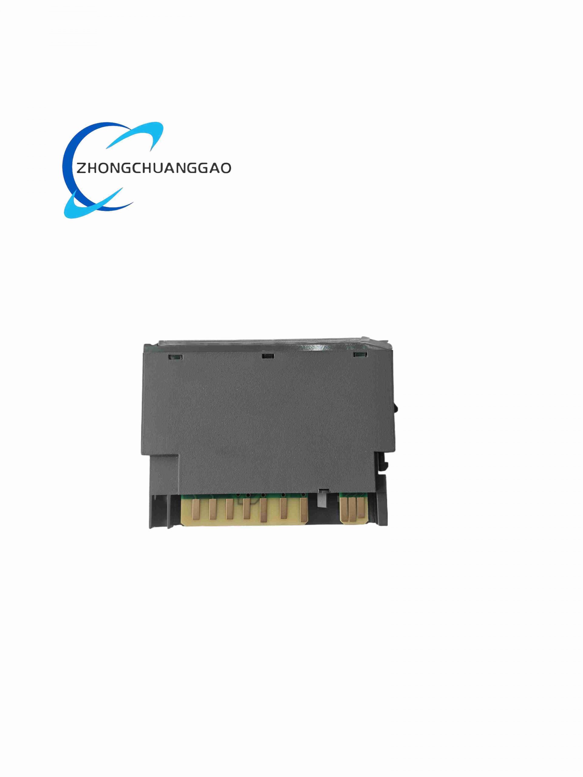
- Rear backplane connector: Gold-plated multi-pin Rockwell CompactLogix standard header
Structural Characteristics
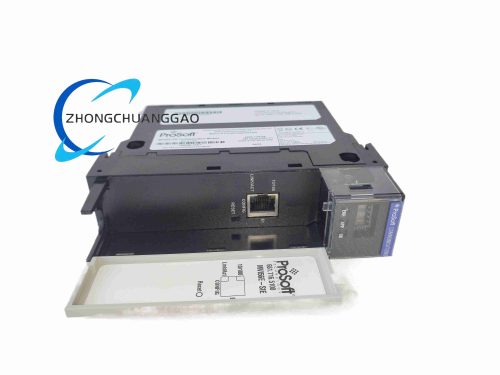
- Standard CompactLogix vertical plug-in single slot module form factor
- Front panel RS485 terminal block + communication status LED indicator array
- Rear edge backplane connector locking latch for rack secure installation
- Single slot footprint occupies minimal rack space for multi-module expansion layouts
Working Principle
Module communicates with CompactLogix CPU via backplane implicit messaging to exchange controller tag data; onboard serial transceiver transmits/receives Modbus RTU frame over RS485 bus to external field devices; internal firmware maps Modbus coil, discrete input, holding register and input register addresses to PLC tag memory address space; diagnostic logic records all serial communication fault events to module internal status registers accessible via PLC ladder logic.
Advantage Highlights
- Native CompactLogix backplane integration eliminates external serial gateway hardware cost
- Software switchable master/slave mode supports dual-direction Modbus data exchange between PLC and third-party equipment
- Comprehensive built-in fault diagnostic counters simplify field communication troubleshooting
- Hot-swappable design reduces production line downtime during module replacement maintenance
- Full compatibility with Studio 5000 Logix Designer programming software without custom driver installation
Applicable Industries
Water treatment plant CompactLogix control systems, HVAC building automation, packaging machinery Modbus drive communication, power meter energy monitoring, food processing batch control, mining local Modbus sensor networks
Installation Requirements
- Insert module into empty single slot of CompactLogix rack, fully engage rear backplane latch lock
- RS485 field wiring use 2-wire shielded twisted pair cable, install 120Ω termination resistor at bus endpoints
- Module firmware version match Studio 5000 software minimum compatible revision
- Maintain 10mm vertical clearance between adjacent rack modules for heat dissipation
- Shield cable single-end grounded at PLC control cabinet earth bar only
Operation & Maintenance Precautions
- Do not connect RS232 electrical level devices to RS485 terminal block pins, permanent transceiver damage occurs
- Bus segment node count strictly limited to maximum 32 Modbus slave devices per module port
- Monthly download communication fault diagnostic data to identify degrading field wiring connections
- Avoid routing RS485 serial cable parallel within 100mm of AC motor power cables
- Module firmware upgrade only performed via official Prosoft configuration software tool
-500x500.jpg)
Reviews
There are no reviews yet.