
Product Short Description
Product Series
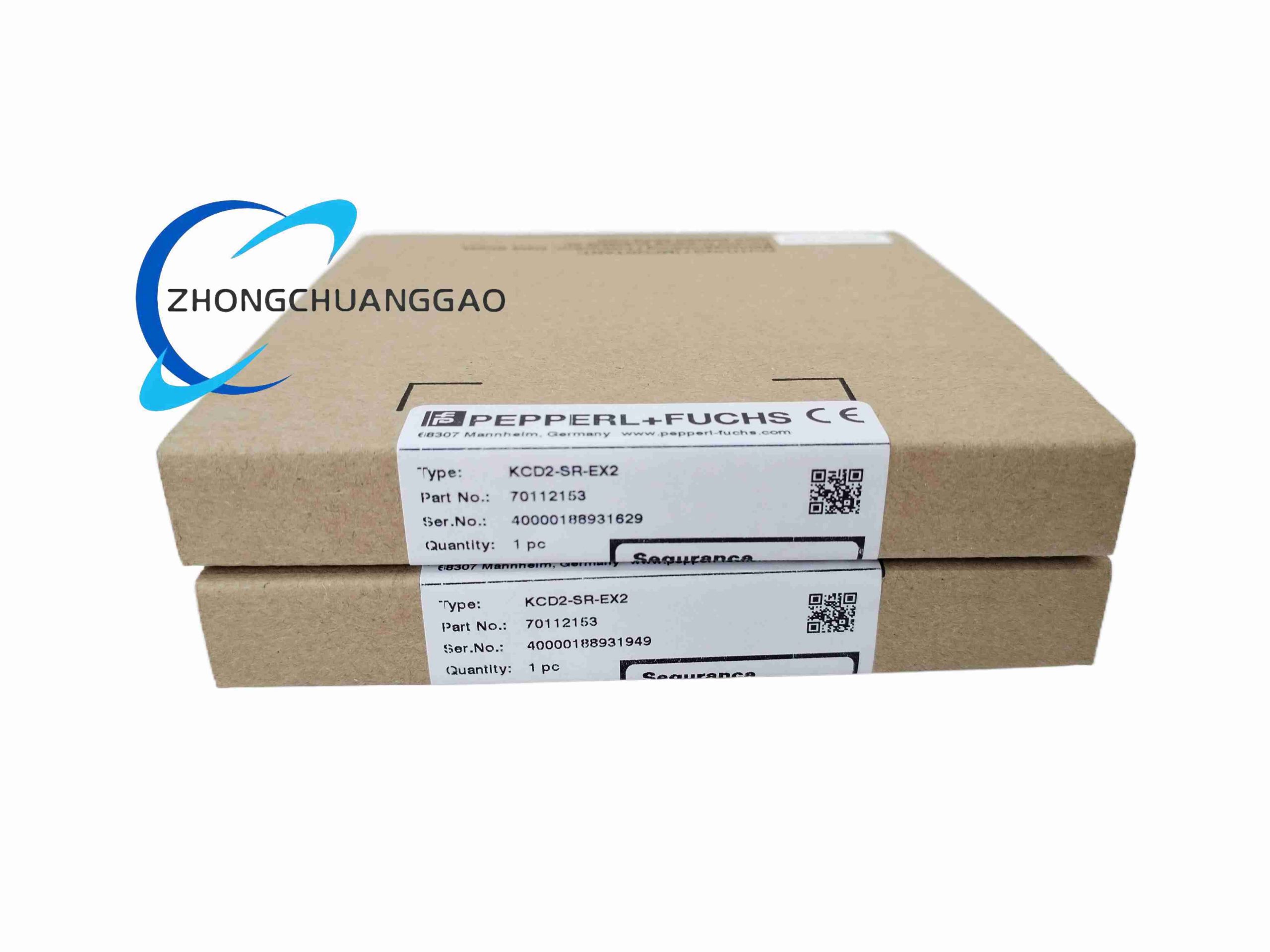
KCD Series Ex Isolation Barriers, HiC282 Safety Family
Product Introduction
DIN rail-mounted galvanic isolated signal barrier for hazardous zone field digital signal transmission. Transmits NAMUR proximity sensor / dry contact binary signals from explosive classified field circuits to safe-area control systems, with integrated line fault detection and SIL 2 functional safety certification.
Description
Technical & Electrical Specifications
- Rated Supply Voltage: 19 V DC ~ 30 V DC
- Max Supply Ripple: ≤ 10%
- Rated Operating Current: ≤ 46 mA
- Max Power Dissipation: ≤ 900 mW
- Field Input Terminal: Terminals 1+,2- / 3+,4- (dual independent channels)
- NAMUR Input Standard: Compliant EN 60947-5-6
- Field Open Circuit Voltage: 8 V DC
- Field Short-Circuit Current: 8 mA
- Switching Threshold: 1.2 mA ~ 2.1 mA; Hysteresis = 0.2 mA
- Line Fault Detection Trigger: Wire break ≤ 0.1 mA; Short circuit ≥ 6.5 mA
- Control Side Relay Output Terminals: 5,6 / 7,8
- Relay Contact Load Rating:
- 253 V AC / 2 A, cosφ > 0.7
- 126.5 V AC / 4 A, cosφ > 0.7
- 30 V DC / 2 A resistive load
- Minimum Switching Current: 2 mA @ 24 V DC
- Actuate / Release Delay: ≤ 20 ms / ≤ 20 ms
- Max Switching Frequency: 10 Hz
- Galvanic Isolation Grade: Reinforced insulation per IEC/EN 61010-1
- Rated Insulation Voltage (All Isolation Boundaries): 300 V eff
- Safety Integrity Level: SIL 2 (SC 3) IEC/EN 61508
Mechanical & Material Specifications
- Overall Dimension (W × H × D): 12.5 mm × 119 mm × 114 mm
- Housing Material: Flame-retardant black polycarbonate, self-extinguishing V0 grade
- Protection Class: IP20 (indoor cabinet use only)
- Mounting Standard: 35 mm DIN rail EN 60715
- Connection Terminal Type: Screw clamp terminals
- Net Weight: Approx. 100 g
- Mechanical Relay Lifespan: 10⁷ switching cycles
Environmental Parameters
- Operating Ambient Temperature: -40 °C ~ +70 °C
- Storage Temperature: -45 °C ~ +80 °C
- Allowed Pollution Degree: Class 2
- Overvoltage Category: II
Function Features
- Dual fully independent signal channels for parallel field sensor acquisition
- DIP switch configurable signal inversion logic
- Secondary relay output configurable as signal mirror or fault alarm output
- Built-in continuous wire break / short-circuit diagnostic monitoring
- Reinforced three-way isolation between field input, power supply, control relay output
- Intrinsically safe Ex ia IIC certification for gas hazardous areas
- Compatible with power rail bus supply or discrete terminal power wiring
Working Principle
Field NAMUR sensor generates variable loop current proportional to target proximity. Internal isolation transformer separates hazardous field circuit from safe control circuit. Onboard comparator converts analog NAMUR current threshold to binary drive signal for mechanical relay contacts. Integrated current sampling circuit continuously monitors loop impedance to trigger line fault relay state change.
Advantage Highlights
- Ultra-narrow 12.5 mm width reduces cabinet space occupation
- SIL 2 certified for safety instrumented system (SIS) loop deployment
- Dual-channel design lowers per-channel installation cost
- Wide -40 °C to 70 °C temperature range supports extreme industrial environments
- Relay output supports high AC/DC load without auxiliary amplifiers
- Standard Ex ia IIC rating compatible with all Class I gas hazard zones
Applicable Industries
Petrochemical refining, natural gas transmission, offshore oil platforms, pharmaceutical batch manufacturing, chemical process plants, mining gas detection, hazardous waste treatment
Installation Requirements
- Mount exclusively inside sealed electrical control cabinets with IP54+ cabinet rating
- Securely clip onto standard 35 mm top-hat DIN rail; horizontal mounting only
- Separate hazardous field wiring and safe-area control wiring via physical cable routing partitions
- All field-side wiring must comply with IEC 60079-14 intrinsic safety wiring regulations
- Supply power must be SELV/PELV 24 V DC regulated power source
- Maintain minimum 10 mm vertical clearance above/below module for heat dissipation
Usage Precautions
- Do not exceed rated relay contact load capacity; derate 30% for inductive loads
- Do not install in locations with direct liquid splash, conductive dust accumulation
- Replace module only during full process shutdown for SIL safety loops
- Avoid parallel connection of multiple barrier field loops without certified isolation calculation
- Calibrate DIP switch configuration prior to energizing field hazardous circuits
- Do not stack heat-generating power modules adjacent without 15 mm gap separation
Reviews
There are no reviews yet.