
Product Short Description
Product Introduction
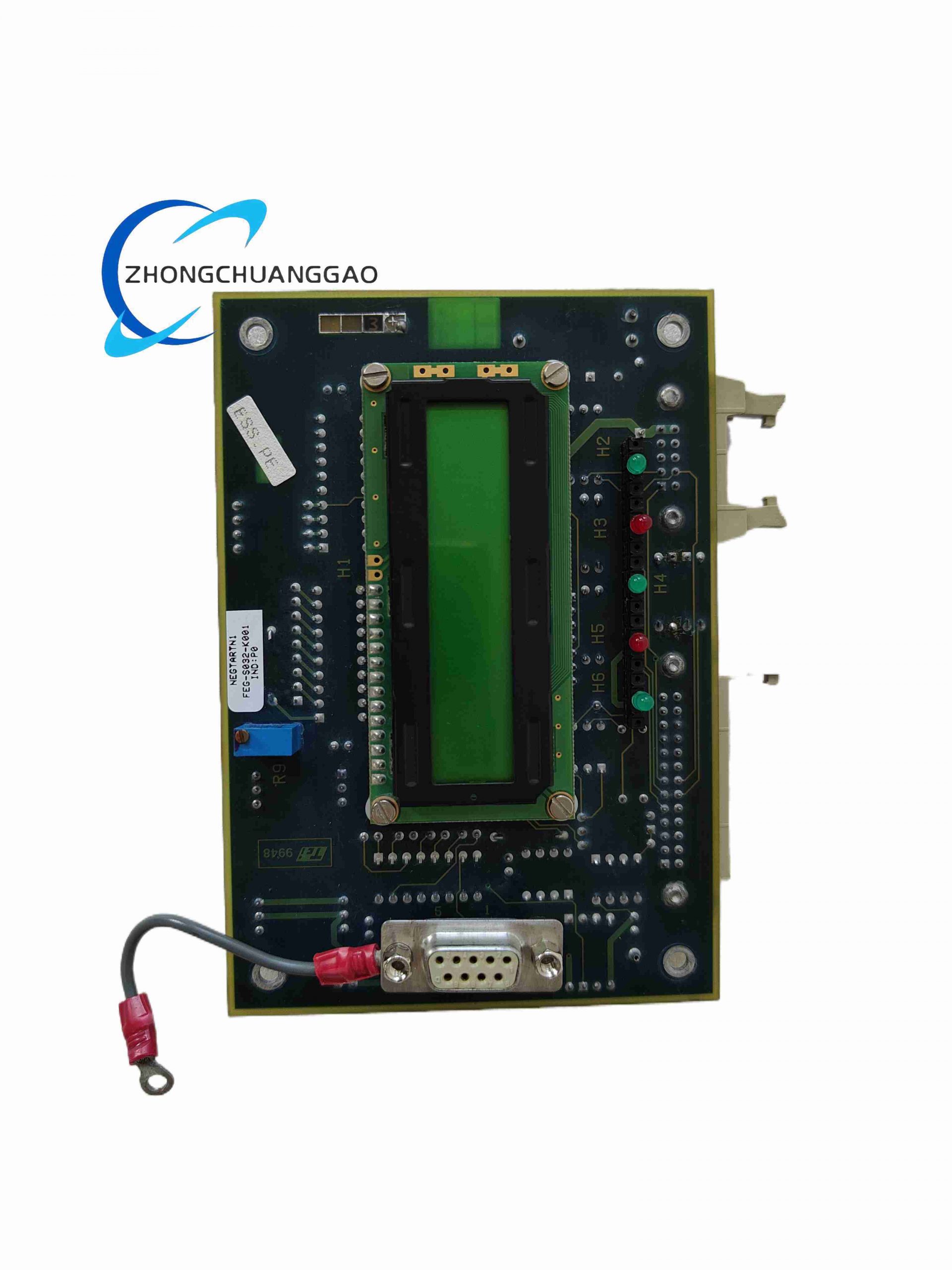
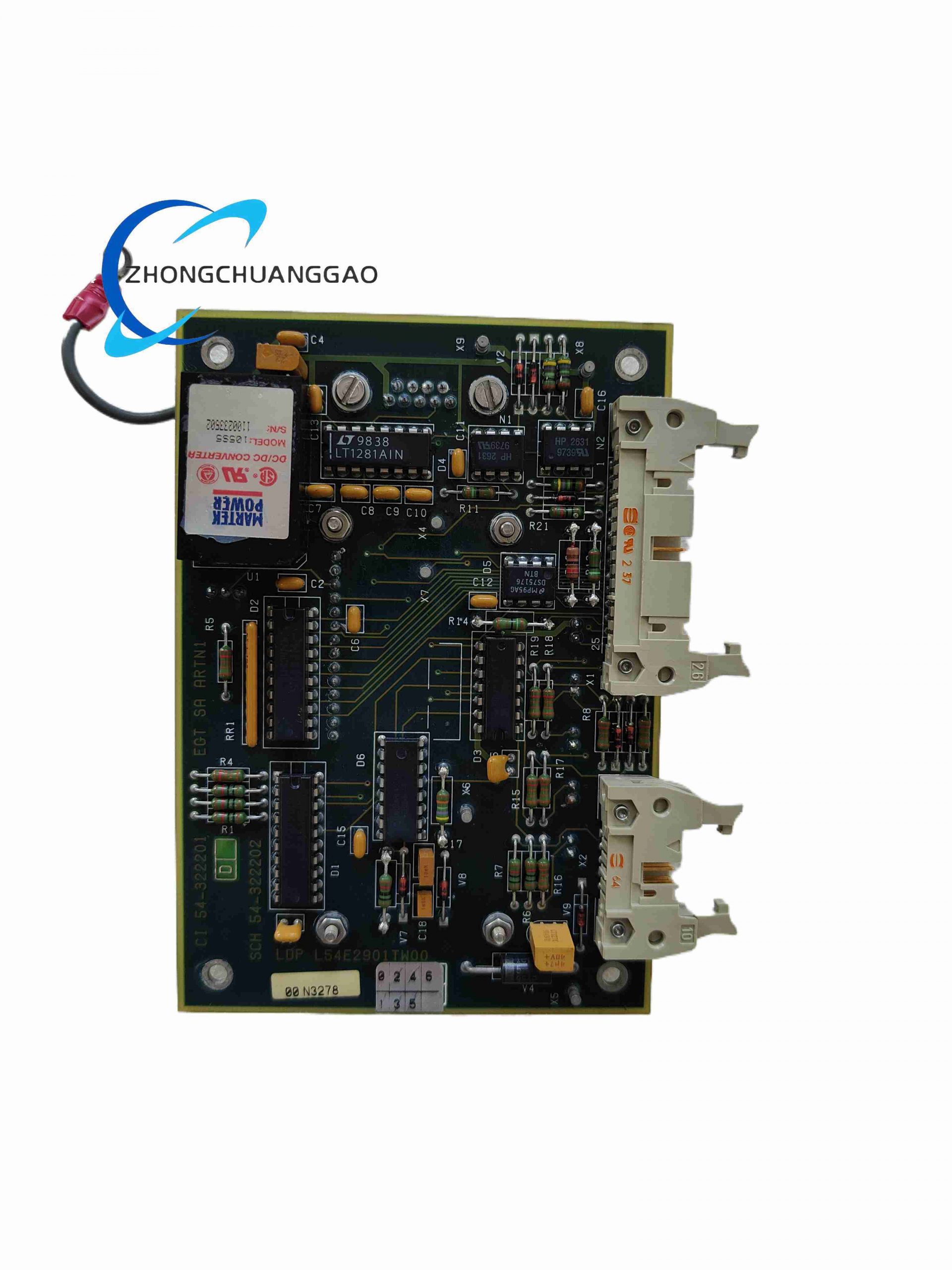
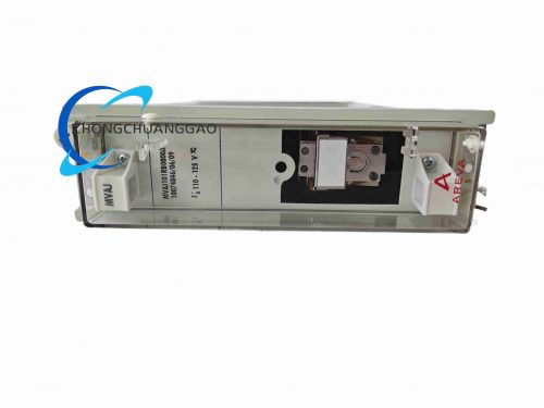
L54E2901TW00 is a core MDEX1 data exchange board for Alstom generator automatic voltage regulator (AVR) excitation control systems. It collects real-time generator voltage, current, frequency and rotor excitation signals from CT/PT sensors, processes excitation regulation logic and transmits control commands to power stage modules for grid stability control of large synchronous generators.
Description
Technical Specifications
- Main Supply Voltage: 110 / 220 V AC dual input power supply
- Auxiliary Logic Supply: 24 V DC ±5%
- Total Power Consumption: Max 32 W
- Operating Temperature Range: -20°C ~ +70°C
- Storage Temperature Range: -40°C ~ +85°C
- Humidity Tolerance: 5% ~ 90% RH non-condensing
- Vibration Resistance: 5–150Hz, 1.5g continuous vibration
- Communication Interface: VME backplane bus, RS485 field sensor bus
- Analog Input Channels: 12 CT/PT isolated measurement channels
- Digital I/O Channels: 16 binary status input, 8 regulation command output
- Galvanic Isolation Rating: 3000V AC between power grid measurement and logic circuit
- PCB Coating: Silicone conformal coating for power plant dust/humidity resistance
Function Features
- Real-time synchronous sampling of generator three-phase voltage and current signals
- Embedded excitation PID regulation algorithm for automatic generator terminal voltage stabilization
- Overvoltage, undervoltage, overcurrent and loss-of-field fault protection logic integration
- VME bus data exchange with main AVR CPU for system parameter configuration and fault recording
- RS485 bus communication with turbine governor and plant DCS system for coordinated grid control
Performance Parameters
- Signal sampling synchronization accuracy: ≤0.1° phase angle error
- Voltage regulation control precision: ±0.5% rated generator terminal voltage
- Fault protection response time: ≤50 ms for severe grid abnormal conditions
- Data communication baud rate: 9600 / 19200 bps configurable RS485
- MTBF: 250,000 hours at nominal power plant operating temperature
- Analog measurement linearity error: ≤0.15% full scale
Material Composition
- PCB substrate: High-Tg FR4 flame retardant glass fiber board
- Surface protection: Silicone conformal anti-corrosion coating
- Isolation components: High voltage reinforced optocouplers
- Power conversion devices: Industrial-grade switching power ICs
- Bus connectors: Gold-plated VME edge connectors and RS485 terminal blocks
- Mechanical frame: Black coated cold rolled steel rack mounting bracket
Structural Characteristics
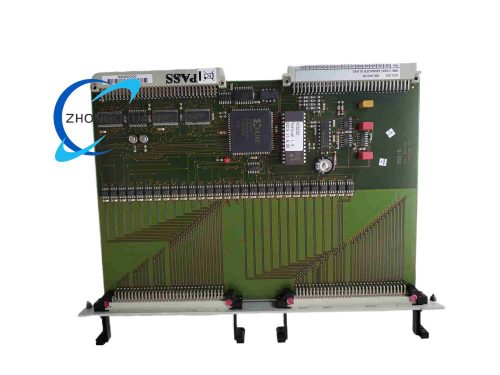
- Standard 6U VME single-width PCB form factor
- Dual power input terminal blocks for redundant AC power supply
- Front panel LED indicators for power status, communication link and fault alarms
- Separate analog measurement zone, digital control zone and power supply zone PCB layout
- Anti-vibration rubber cushion mounting lugs for power plant cabinet installation
Working Principle
Current transformer (CT) and voltage transformer (PT) signals are isolated and sampled by analog front-end circuits; digital processing unit executes excitation closed-loop PID regulation logic to calculate required rotor excitation current output. Measured generator operating parameters and fault codes are transmitted via VME bus to main AVR controller and via RS485 to plant distributed control system for real-time monitoring and grid coordination control.
Advantage Highlights
- High voltage isolation eliminates grid surge damage to internal logic circuits
- Integrated full-set generator excitation fault protection logic without auxiliary external modules
- Silicone conformal coating resists power plant dust, humidity and corrosive flue gas
- Dual redundant AC power supply input prevents single power source outage shutdown
- Native compatibility with all Alstom large steam, gas and hydro generator AVR systems
Applicable Industries
Thermal power plants, hydroelectric power stations, gas turbine combined cycle power plants, industrial captive generator power stations
Installation Requirements
- Mount inside IP44 rated power plant control cabinet with dust filtering ventilation
- Secure PCB rack mounting screws to 1.0 N·m torque to resist unit vibration
- CT/PT signal wiring must use shielded twisted pair cable with single-point cabinet ground
- Separate high-voltage measurement wiring from low-voltage logic signal wiring with minimum 30cm separation
- Cabinet ambient temperature maintained below 60°C for continuous full-load operation
Usage Precautions
- Cut off both AC main power and 24V DC auxiliary power before card removal or wiring modification
- Calibrate CT/PT analog input channels every 24 months to maintain measurement accuracy
- Avoid exposure to sulfur-containing corrosive gas in coal-fired power plant cabinets
- Do not short-circuit CT secondary terminals during maintenance to prevent high voltage surge hazards
- Store spare boards in constant temperature dry cabinet with anti-static packaging
Reviews
There are no reviews yet.