
Product Short Description
Product Introduction
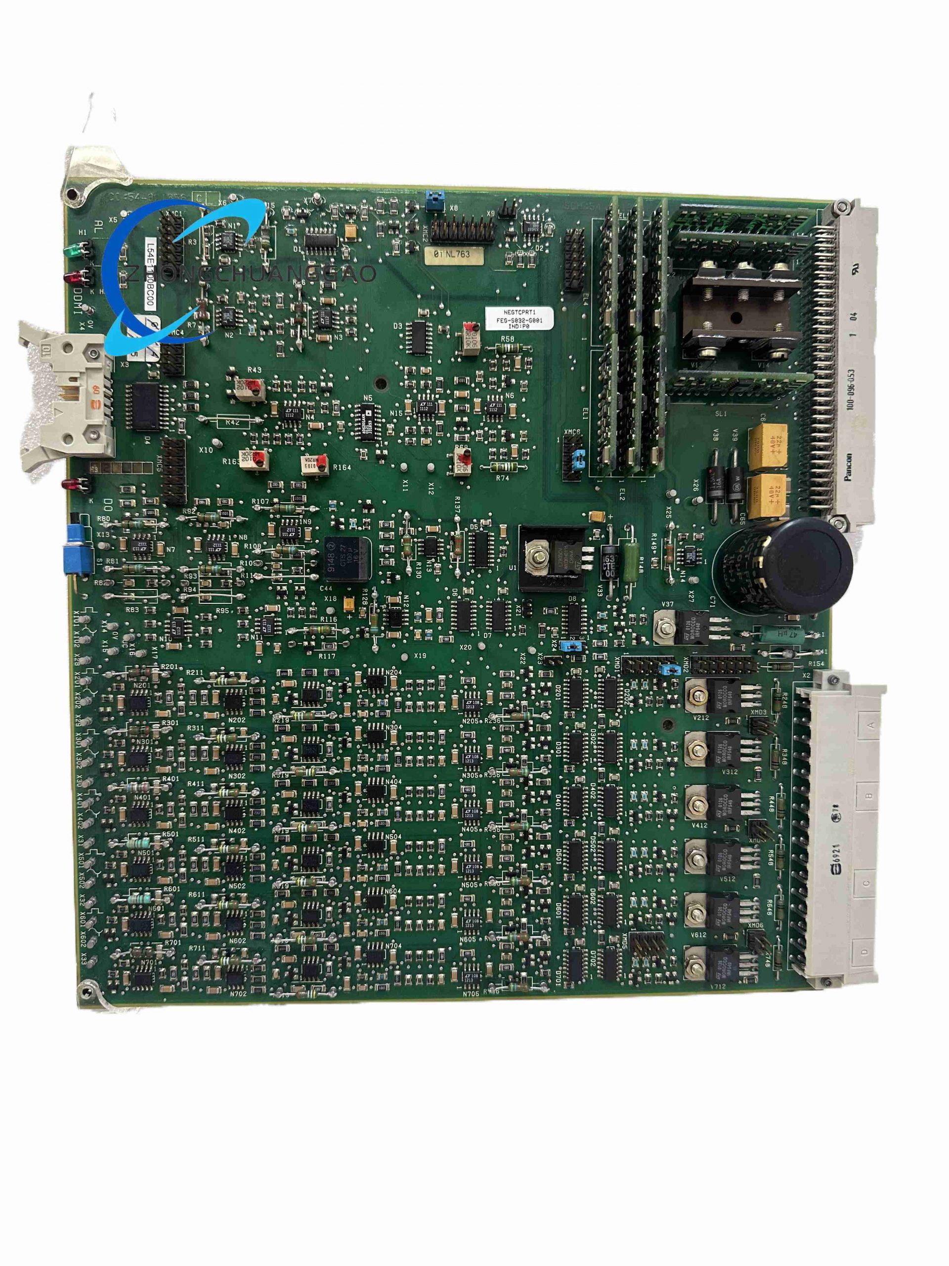
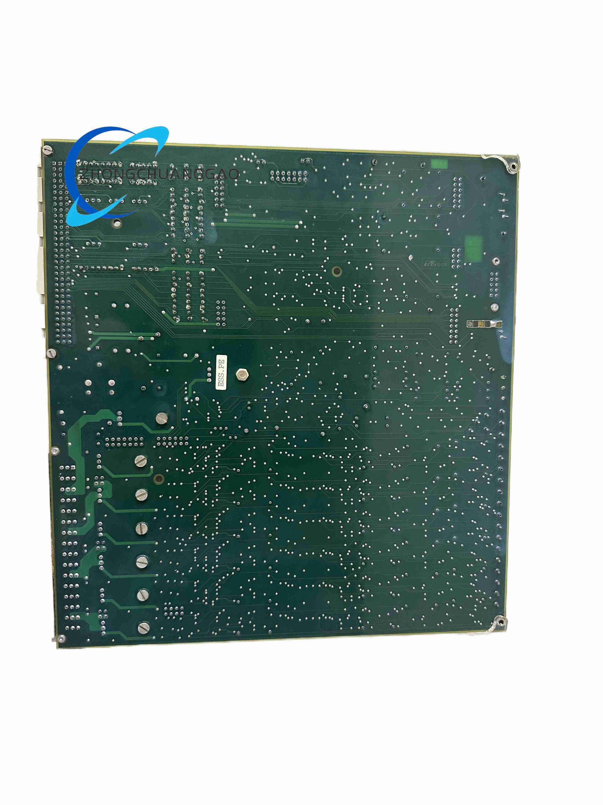
L54E1100BC00 is a SIL4 certified vital safety input/output circuit board manufactured by Alstom, dedicated to railway interlocking, train control and trackside safety signaling systems. It performs high-speed acquisition of track circuit, axle counter and signal lamp analog/digital vital signals, executes fail-safe logic processing and outputs safety-critical drive commands to field signaling equipment.
Description
Technical Specifications
- Safety Integrity Level: SIL4 (EN 50128 / EN 50129)
- Operating Supply Voltage: 24 V DC ±10%
- Power Consumption: Max 18 W
- Operating Temperature Range: -20°C ~ +70°C
- Storage Temperature Range: -40°C ~ +85°C
- Humidity Tolerance: 5% ~ 95% RH non-condensing
- Vibration Resistance: 10–200Hz, 2g continuous vibration
- Shock Resistance: 15g peak shock (11ms pulse)
- Communication Bus: VME industrial backplane bus
- Input Channels: 16 galvanically isolated analog vital input channels
- Output Channels: 8 fail-safe relay output channels
- Isolation Voltage: 2500V AC between field circuit and backplane bus
- PCB Protection Coating: Conformal acrylic coating (IP30 internal cabinet rating)
Function Features
- Dual redundant signal sampling circuit for 100% fail-safe operation
- Continuous self-testing of input/output channels every 10ms to detect open/short circuit faults
- Hardware interlock logic prevents dangerous false output actuation under single component failure
- Galvanic isolation between field wiring and control backplane eliminates ground loop interference
- Real-time fault diagnosis data transmitted via VME bus to main interlocking CPU
Performance Parameters
- Signal sampling cycle: 10 ms deterministic fixed cycle
- Channel fault detection response time: ≤20 ms
- Relay output switching life: ≥10⁷ mechanical operations
- Analog input measurement accuracy: ±0.2% full scale
- Common-mode noise rejection ratio: ≥120 dB
- MTBF: 220,000 hours at 40°C operating temperature
Material Composition
- Base substrate: FR4 high-Tg flame retardant PCB
- Surface coating: Acrylic conformal protective coating
- Signal relays: Silver alloy contact safety relays
- Isolation components: High withstand voltage optocouplers
- Backplane connector: Gold-plated copper alloy edge connector
- Enclosure: Aluminum alloy rack guide rail frame
Structural Characteristics
- Standard 6U VME single-width PCB form factor
- Front panel with LED status indicators for each channel
- Screw terminal block for field wiring on front panel
- Back edge VME bus connector for rack data communication
- Reinforced mounting lugs for rack vibration resistance
- Separate analog signal zone and digital logic zone PCB layout
Working Principle
Dual independent sampling circuits simultaneously read field vital signals; hardware comparator cross-checks dual sampling values to identify signal faults. All output drive circuits implement fail-safe de-energized design: any internal component failure de-energizes safety relays to cut off dangerous field output signals, complying with railway vital safety fail-to-dark logic.
Advantage Highlights
- Full SIL4 compliance for highest railway safety standard applications
- Integrated channel self-test without external auxiliary equipment
- Conformal coating enables stable operation in damp tunnel trackside cabinets
- VME bus compatibility with all Alstom Microrec interlocking racks
- Hardware safety logic independent of software CPU to eliminate software single point of failure
Applicable Industries
Mainline railway signaling, metro subway interlocking, light rail transit, high-speed rail trackside safety control
Installation Requirements
- Install inside IP54 rated sealed industrial control cabinet only
- Mount on standard 6U VME rack with fixed rail locking screws
- Field wiring torque limit: 0.6 N·m for terminal block screws
- Separate safety signal wiring from power cables with minimum 20cm clearance
- Cabinet internal forced air cooling required for continuous operation above 55°C ambient
Usage Precautions
- Complete power cut to rack before card insertion/removal to avoid backplane bus damage
- Do not operate outside -20°C ~ +70°C temperature range; high temperature accelerates relay contact aging
- Prevent liquid ingress and conductive dust accumulation on PCB surface
- Regular annual cleaning of front panel terminal blocks to avoid oxidation contact resistance
- Replace card immediately upon continuous channel fault alarm; no field repair of PCB components permitted
-500x500.jpg)
Reviews
There are no reviews yet.