
Description
Product Overview
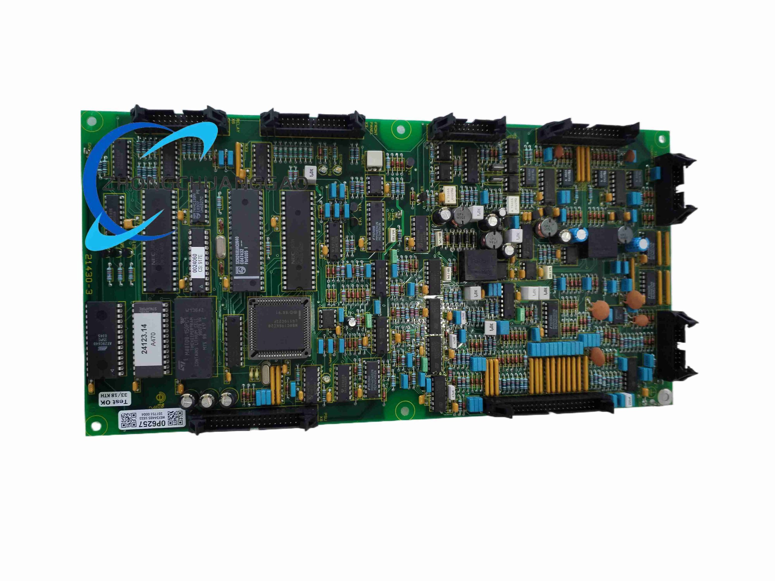
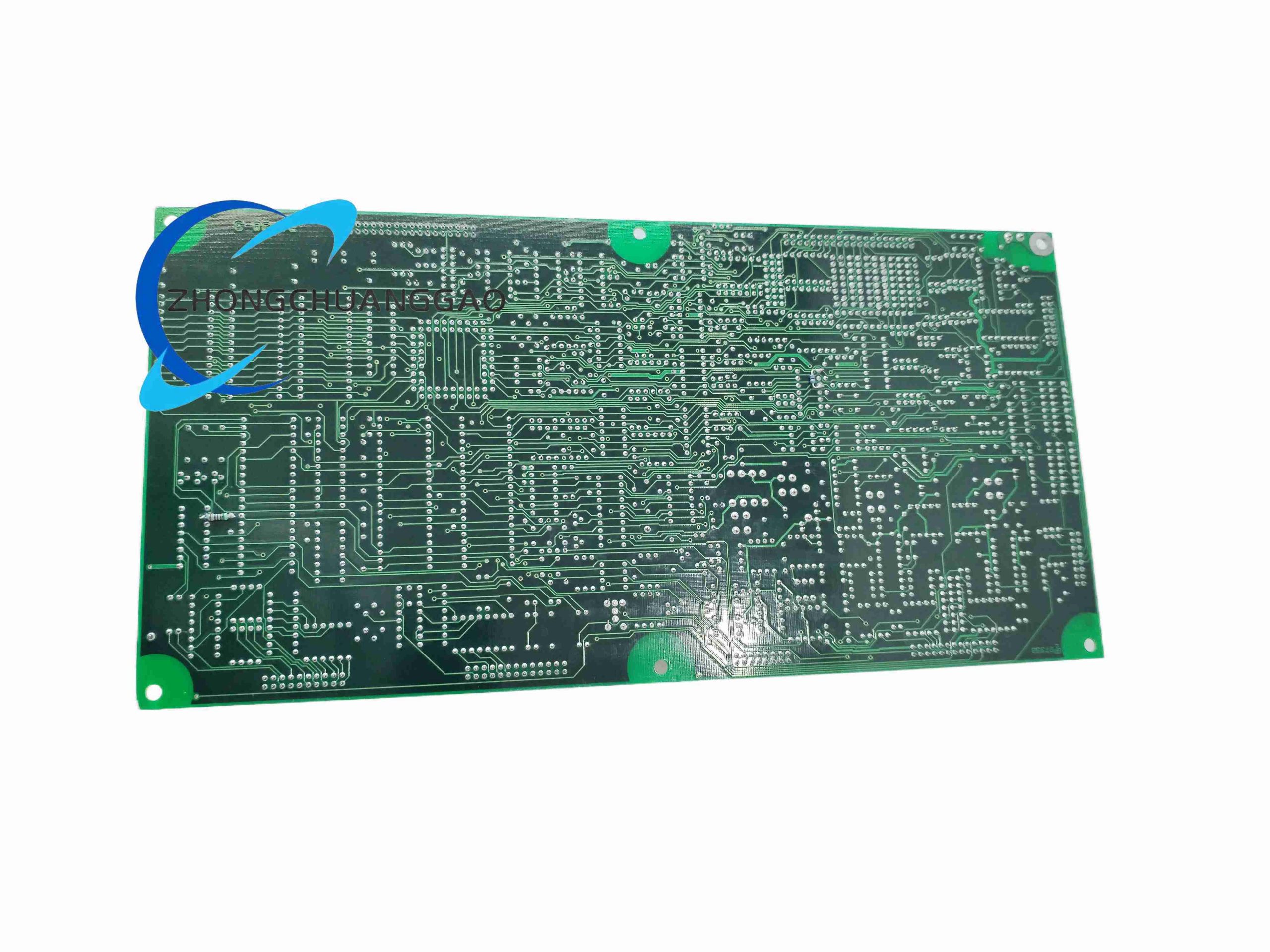
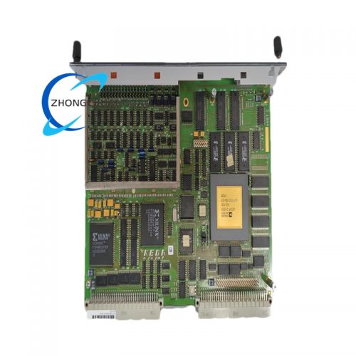
Core printed circuit board regulator control unit exclusively integrated into GUTOR industrial DC battery charging and uninterruptible power supply systems deployed in nuclear power, thermal power, and critical industrial process safety infrastructure. The board executes closed-loop voltage/current regulation, system fault diagnostics, remote SCADA communication, and battery protection logic for high-reliability 24/48/110/220 VDC backup power plants.
Technical Specifications
- Onboard Processing Core: High-speed 32-bit real-time industrial microcontroller
- Regulation Output Voltage Accuracy: ±1% full operating load range
- Maximum Continuous Regulator Control Current Bandwidth: 15 A nominal, 22 A 5-second peak transient
- Output Ripple & Noise Floor: <50 mVpp across 20 Hz–20 MHz measurement spectrum
- Supported DC System Bus Voltages: 24 VDC, 48 VDC, 110 VDC, 125 VDC, 220 VDC configurable via onboard DIP switches
- Industrial Communication Protocols: Modbus TCP/RTU, Profibus DP, Ethernet/IP
- Maximum Expandable Digital/Analog I/O Capacity: 384 total system monitoring points
- Operating Temperature Range: 0 °C to +55 °C cabinet ambient
- Storage Temperature Range: -20 °C to +70 °C
- Physical PCB Dimension (W×H): 110 mm × 160 mm
- PCB Substrate Thickness: 1.6 mm FR4 UL94-V0 flame retardant
- Unit Gross Weight: 1.0 kg
Material Composition
- Main Circuit PCB: High-Tg FR4 halogen-free fire-resistant laminate with tin-lead-free surface finish
- Power Regulation Semiconductors: Low ESR silicon MOSFET switching transistors
- Signal Isolation Components: 2500 VAC reinforced optocoupler isolation barriers
- Terminal Header Connectors: Gold-plated phosphor bronze contact pins with anti-vibration locking latches
- Surface Mount Passive Components: Industrial-grade wide-temperature range resistors and ceramic capacitors
Structural Characteristics
- Standard pluggable rack card form factor compatible with GUTOR SDC series power system backplane racks
- Segregated high-power regulation zone and low-voltage signal monitoring zone separated by PCB ground isolation moats
- Front panel LED status indicators for power, charging, battery fault, overvoltage, undervoltage, and communication loss alarms
- DIP switch bank for on-site configuration of DC bus voltage rating, battery type, and charging curve parameters
- Dual redundant communication bus connectors for hot-backup system architectures
Working Principle
The onboard microcontroller continuously samples DC bus voltage, charging output current, and battery terminal temperature via isolated analog acquisition circuits. Closed-loop PID regulation algorithms dynamically adjust the pulse-width modulation duty cycle of the primary power switching stage to maintain precise constant float/boost charging voltage for lead-acid, nickel-cadmium, and lithium industrial battery banks. Integrated fault logic detects overvoltage, undervoltage, overcurrent, battery over-temperature, and mains input loss conditions, activating hardware interlock cutout circuits and transmitting alarm telemetry data to remote SCADA monitoring systems via standard industrial communication buses.
Function & Feature Highlights
- Multi-battery type configurable charging curve profiles (float, boost, equalization charge modes)
- Real-time battery temperature compensation regulation preventing overcharging under high ambient conditions
- Dual redundant communication bus interfaces for fault-tolerant remote monitoring and control
- Complete system fault diagnostic logging with timestamped fault history storage on onboard flash memory
- Isolated analog and digital signal acquisition eliminating ground loop interference in multi-rack power systems
- Hot-swappable rack card design for live power system maintenance without full plant power shutdown
Core Advantages
- Swiss OEM industrial power grade construction certified for nuclear and critical energy infrastructure deployment
- Reinforced electrical isolation between high-voltage DC power circuits and low-voltage monitoring signal paths
- Wide configurable DC bus voltage range compatible with all standard industrial backup power plant specifications
- Modular expandable I/O architecture scalable from single rack to multi-unit parallel redundant power systems
- Compliance with IEC 61010-1 industrial power safety standard and UL functional safety certification
Applicable Industries
Nuclear power station auxiliary DC power systems, thermal power plant switchgear backup UPS, petrochemical process safety ESD emergency shutdown power supply, railway signaling backup power, offshore oil platform critical instrumentation power, data center industrial DC backup battery systems
Installation Requirements
- Horizontal rack card insertion orientation only; vertical mounting causes passive component thermal sag and long-term solder joint fatigue
- Minimum 20 mm horizontal spacing between adjacent control cards for cross-flow cooling air circulation
- All signal wiring must use twisted shielded pair cable to suppress high-frequency switching noise interference
- Backplane power bus connectors must be fully seated to eliminate intermittent voltage regulation drift faults
- Onboard DIP switch configuration must match connected battery bank nominal voltage before rack energization
Usage Precautions
- Operating cabinet ambient humidity must stay below 95% non-condensing; condensation creates conductive leakage across PCB isolation moats triggering short-circuit protection
- Card removal/insertion during live system operation must follow manufacturer hot-swap interlock sequence to avoid transient voltage spikes damaging acquisition circuits
- Do not modify onboard surface-mount resistors or capacitors; component alteration voids OEM safety certification and regulation accuracy
- Annual calibration of analog voltage/current acquisition circuits mandatory for nuclear and critical energy facility deployments
- Maximum operating altitude limited to 1000 meters without power regulation output derating
Reviews
There are no reviews yet.