
Product Short Description
Product Introduction
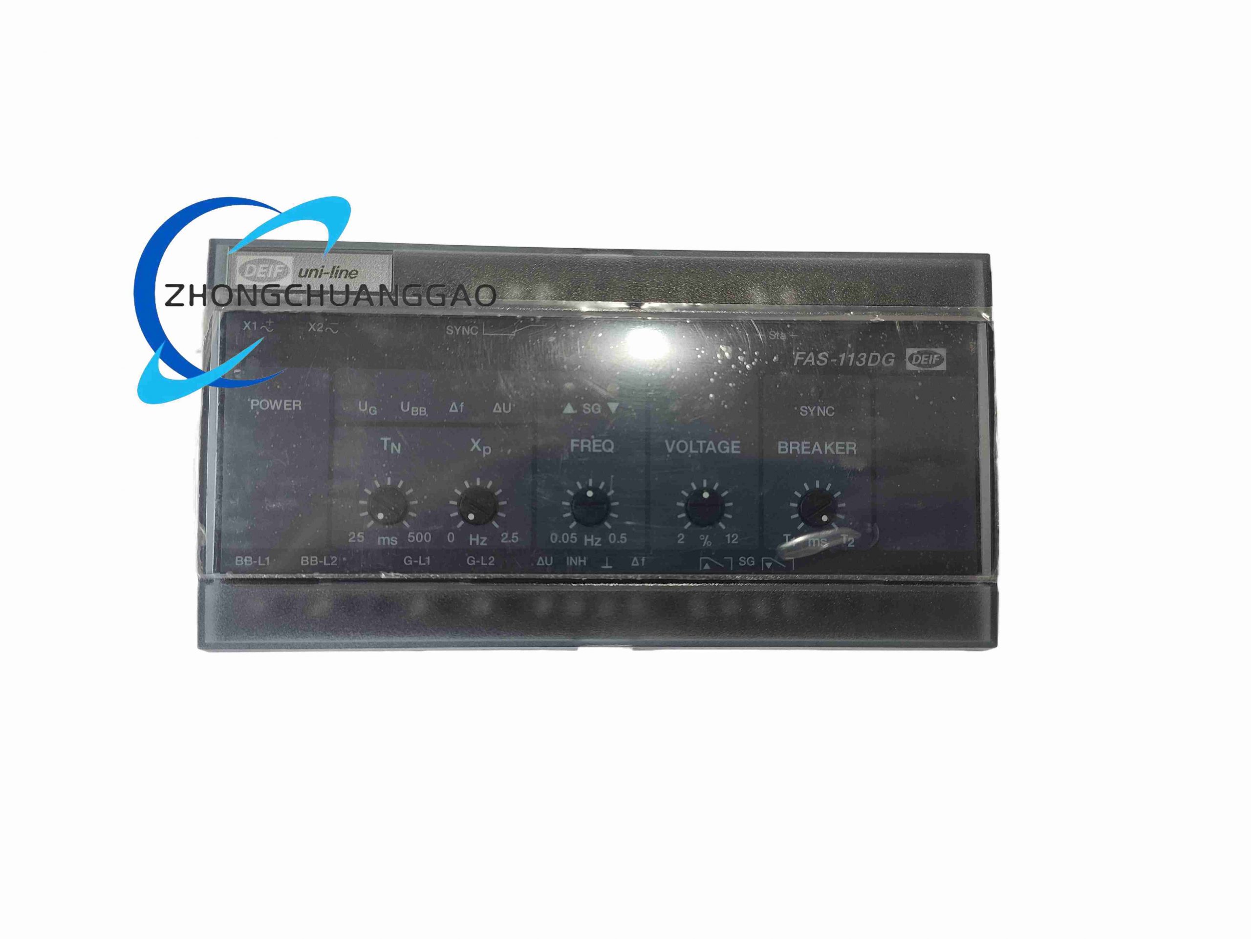
DEIF FAS-113DG is an industrial-grade multi-channel automatic synchronizer master controller designed for multi-generator station parallel operation. It executes high-precision voltage, frequency, phase angle matching between generator and mains busbar, provides adjustable governor and excitation control outputs, breaker closing time compensation, and complete electrical fault protection functions.
Description
Technical Specifications
- Power Supply Input: 18 V DC – 32 V DC nominal 24 V DC
- Maximum Power Consumption: 7 W
- AC Voltage Measurement Input: Single/three-phase auto-detect 0–480 V AC
- Frequency Measurement Bandwidth: 40 Hz – 75 Hz
- Adjustable Synchronization Parameters:
ΔU threshold: 1 % – 15 % rated voltage
Δf slip frequency: 0.02 Hz – 1.0 Hz
Max allowable phase offset: 1° – 30° electrical
Breaker closing delay compensation: 0 ms – 1000 ms
- Digital Input Channels: 6 opto-isolated 24 V DC digital inputs
- Analog Input Channels: 3 isolated analog measurement inputs
- Digital Output Relays: 6 relay contact outputs (5 A @ 250 V AC)
- Analog Control Outputs: 3 0–10 V DC proportional trim outputs for governor/AVR
- Communication Interface: Galvanically isolated RS485 Modbus RTU
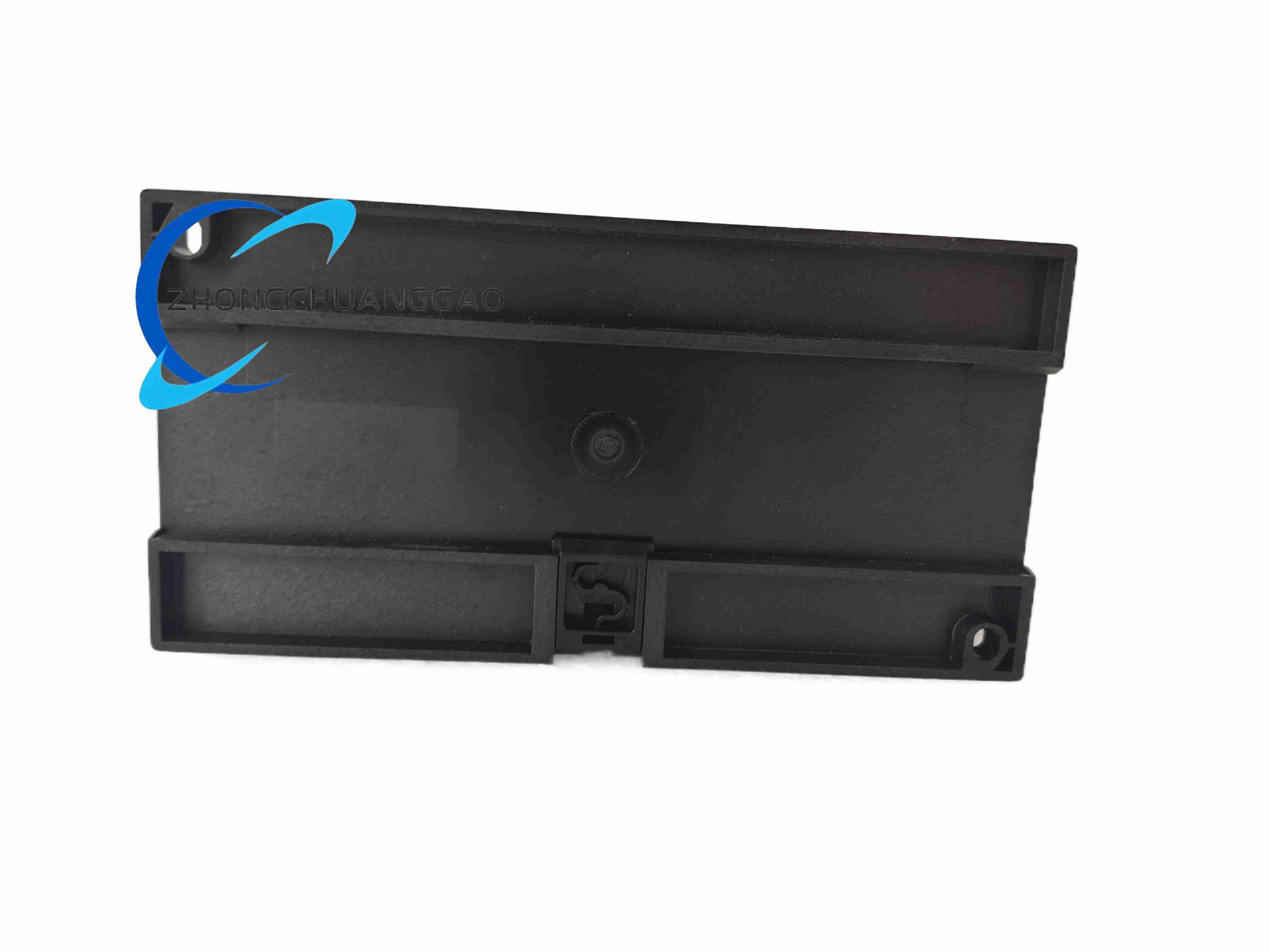
- Mounting Type: 35 mm DIN rail or base plate bolt mounting
- Module Physical Dimensions: 140 mm × 86 mm × 34 mm
- Unit Weight: 0.75 kg
- Operating Temperature Range: -25 °C ~ +70 °C
- Storage Temperature Range: -40 °C ~ +85 °C
- Humidity Rating: 95 % RH non-condensing
- Certifications: CE, IEC 61000, DNV, Lloyd’s Register marine certification
Function Features
- Single/three-phase automatic waveform detection for flexible genset configuration
- Multi-stage governor speed trim and AVR voltage proportional analog control outputs
- Adjustable pulse duration for fast-response gas turbines and slow-response diesel engines
- Full suite of protection functions: over/under voltage, over/under frequency, reverse power, phase sequence fault
- RS485 Modbus communication for SCADA system remote monitoring and parameter configuration
- Comprehensive front-panel LED diagnostic array for all measurement and fault status signals
- Configurable manual synchronization mode with locked parameter safety limits
- Built-in ESD and overvoltage surge protection for all input/output terminals
Performance Parameters
- AC waveform sampling frequency: 200 Hz high-speed real-time scan
- Phase angle measurement resolution: 0.05° electrical precision
- Analog trim output linearity error: ≤ 0.5 % full scale
- Relay mechanical switching lifespan: ≥ 1,200,000 operating cycles
- Modbus communication maximum cable length: 200 m with 120 Ω termination resistor
Material Composition
- Enclosure housing: Reinforced glass-filled PA66 UL94-V0 flame retardant plastic
- Circuit board: Double-sided FR4 PCB with full tin plating for corrosion resistance
- Terminal blocks: Spring-cage nickel-plated copper screw terminals
- Isolation transformers: Laminated silicon steel low-loss voltage isolation transformers
Structure Characteristics
- Standard DIN rail vertical enclosure with dual-row front wiring terminal blocks
- Separate internal circuit partitions for high-voltage AC measurement, low-voltage control logic, and communication circuits
- Front panel sealed calibration access ports for parameter adjustment without enclosure disassembly
Working Principle
Isolated voltage transformers acquire generator and busbar three-phase voltage waveforms; onboard 32-bit microcontroller continuously calculates RMS voltage, fundamental frequency, phase sequence, and instantaneous phase differential. Proportional analog trim signals adjust engine governor fuel supply and generator excitation voltage to eliminate synchronization mismatches. Once all differential parameters enter user-defined tolerance windows, the controller applies preprogrammed breaker mechanical delay compensation and transmits timed closing relay output pulse. Integrated reverse power monitoring continuously detects negative power flow and immediately blocks closing commands if reverse power thresholds are breached.
Advantage Highlights
- Three-phase auto-detection compatible with all industrial stationary power station gensets
- Analog proportional governor/AVR trim delivers smoother synchronization than pulse-only control modules
- Marine classification society certified for offshore platform and large cargo vessel power systems
- RS485 Modbus interface enables full remote parameter tuning and real-time data logging
- Extended adjustable breaker compensation range supports slow heavy-duty industrial circuit breakers
- Six digital input channels accept auxiliary switch feedback signals for complete interlock logic
Applicable Industries
Thermal power auxiliary stations, natural gas cogeneration plants, industrial multi-genset backup power facilities, offshore oil platform power systems, commercial marine vessel main switchboards, peak-shaving grid parallel power plants
Installation Requirements
- Mount to standard 35 mm DIN rail or flat steel base plate with M4 mounting bolts
- AC voltage sensing cables must be shielded twisted-pair with single-end shield grounding
- Separate wiring ducts for high-voltage AC measurement lines and DC control power wiring
- Install 5 A circuit breaker protection on 24 V DC power supply input terminal
- RS485 communication cable must use dedicated twisted-pair fieldbus cable with bus-end termination resistor
Usage Notes
- All three-phase voltage inputs must be wired in matching phase sequence to avoid synchronization failure
- Complete parameter backup via Modbus software before module replacement or firmware update
- Conduct full synchronization performance test after every genset governor/AVR overhaul
- Avoid mounting within 200 mm of large AC contactors or variable frequency drives
- Store spare controllers in temperature-controlled dry environment to prevent PCB corrosion
Reviews
There are no reviews yet.