
Product Short Description
Product Introduction
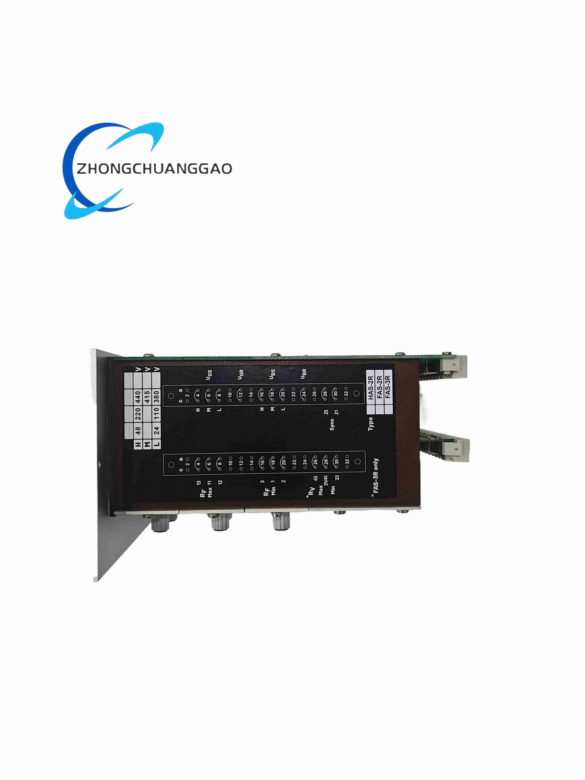
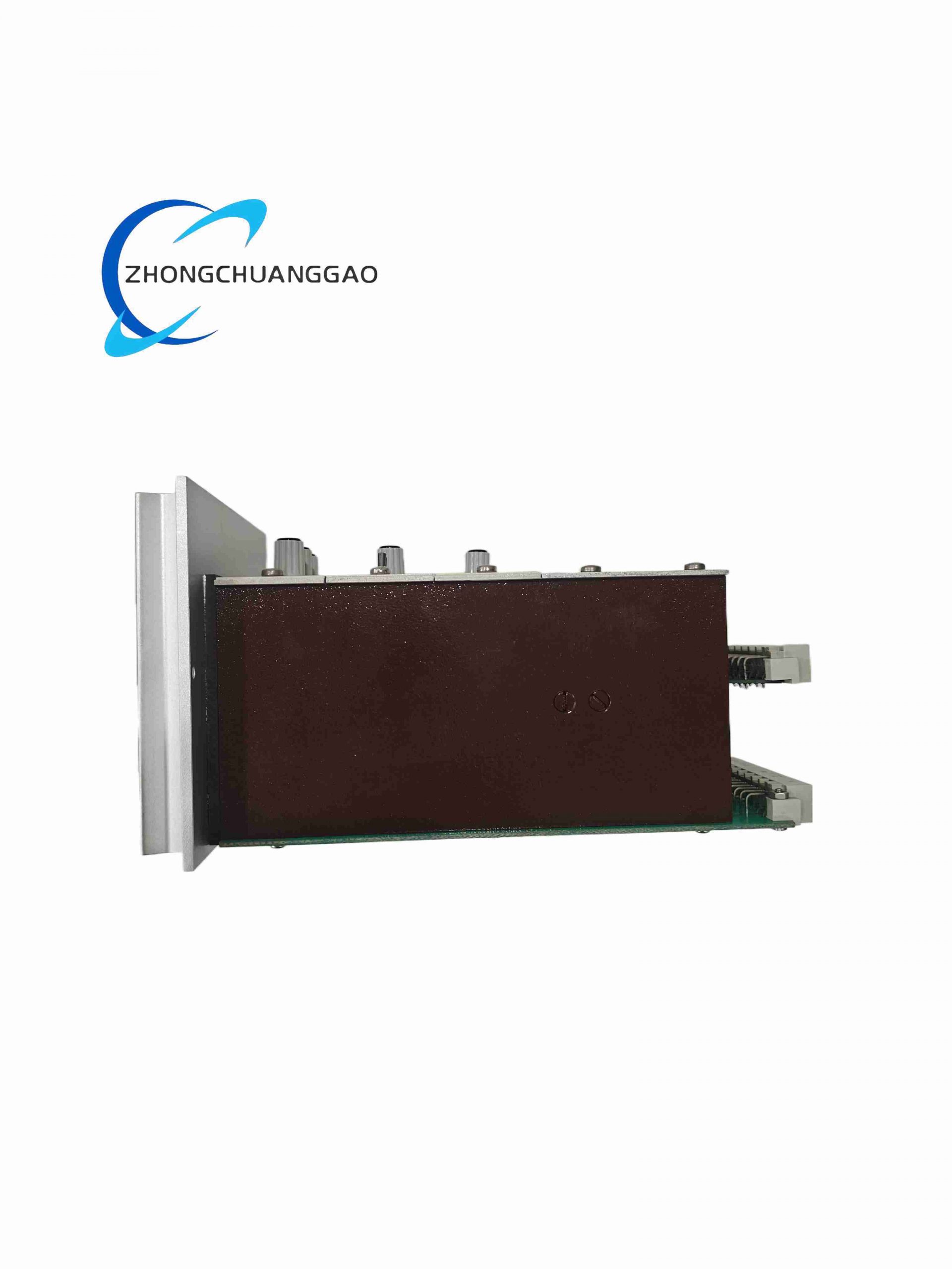
DEIF FAS-2R is a compact DIN-rail mounted automatic synchronizer module dedicated to small single-generator parallel power systems. It continuously measures voltage, frequency, and phase angle difference between generator output and utility/switchgear busbar, automatically adjusting engine governor speed and excitation voltage to achieve synchronization and output timed closing pulse signals to generator circuit breakers. It provides full anti-reverse power protection to eliminate damaging cross-current during paralleling operations.

Description
Technical Specifications
- Power Supply Voltage: 18 V DC – 32 V DC nominal 24 V DC
- Maximum Power Consumption: 4 W
- Voltage Measurement Input Range: 0 – 480 V AC single-phase
- Frequency Measurement Range: 40 Hz – 70 Hz
- Adjustable Synchronization Thresholds:
Max allowable voltage difference ΔU: 2 % – 10 % rated
Max allowable slip frequency Δf: 0.05 Hz – 0.5 Hz
Max allowable phase angle difference: 2° – 20° electrical
- Circuit Breaker Closing Time Compensation: 0 ms – 500 ms adjustable
- Output Relay Contacts Rating: 5 A @ 250 V AC resistive load
- Mounting Standard: 35 mm DIN rail mounting
- Physical Dimensions: 110 mm × 75 mm × 40 mm
- Module Weight: 0.45 kg
- Operating Temperature Range: -25 °C ~ +70 °C
- Storage Temperature Range: -40 °C ~ +85 °C
- Humidity Tolerance: 95 % RH non-condensing
- Vibration Compliance: 2–13.2 Hz ±1 mm displacement; 13.2–100 Hz ±0.7 g acceleration
- Certifications: CE, IEC 60034, DNV marine type approval
Function Features
- Single-phase voltage/frequency/phase real-time three-parameter synchronization monitoring
- Automatic governor raise/lower pulse output for generator frequency matching
- Adjustable excitation voltage trim output for voltage difference correction
- Precisely timed breaker closing pulse with built-in mechanical delay compensation
- Anti-parallel reverse power interlock inhibits closing command under out-of-tolerance conditions
- Front panel multi-color LED indicators for bus voltage, generator voltage, slip frequency, sync condition, fault alarm
- Overvoltage, undervoltage, overfrequency, underfrequency continuous protection logic
- Manual synchronization override mode for commissioning and maintenance testing
Performance Parameters
- Synchronization measurement sampling rate: 100 Hz real-time scan
- Phase angle detection resolution: 0.1° electrical
- Closing pulse output duration: 100 ms – 2000 ms user configurable
- Relay mechanical service life: ≥ 1,000,000 switching cycles
- Measurement total harmonic distortion tolerance: ≤ 25 % input THD without accuracy degradation
Material Composition
- Front housing: Grey PA66 flame retardant plastic, UL94-V0
- Internal PCB: FR4 fiberglass substrate with tin-lead free plating
- Terminal contacts: Nickel-plated copper alloy screw terminal blocks
- Internal transformers: Silicon steel laminated isolation voltage transformers
Structure Characteristics
- Compact vertical DIN rail enclosure with front-facing wiring terminal block
- Integrated front panel status LED array and small calibration potentiometer adjustment ports
- Internal isolated transformer compartment separating high-voltage AC measurement circuits from low-voltage control logic
Working Principle
Separate isolated voltage transformers sample generator terminal voltage and busbar voltage signals. Onboard microcontroller continuously calculates instantaneous frequency, RMS voltage, and real-time phase angle offset between the two AC waveforms. If measurement values exceed preconfigured synchronization thresholds, the module outputs proportional raise/lower pulse signals to engine governor and AVR excitation regulator to eliminate differential parameters. When all three synchronization parameters fall within set limits, the module calculates breaker mechanical closing delay and transmits timed closing relay pulse to engage generator parallel connection switchgear.
Advantage Highlights
- Ultra-compact DIN rail design fits small generator control panel enclosures
- Built-in three-way automatic adjustment eliminates separate governor/AVR trim controllers
- DNV marine certification permits direct deployment on yacht, vessel, and offshore small generator sets
- Wide DC supply range compatible with standard 12 V / 24 V generator battery systems
- Simple potentiometer calibration without dedicated programming software
- Low power draw minimizes standby battery load during generator idle periods
Applicable Industries
Marine leisure vessel power systems, residential backup generator parallel panels, small commercial prime power gensets, construction site temporary power units, remote telecom tower backup power
Installation Requirements
- Secure mounting on standard 35 mm top-hat DIN rail inside IP54 rated control enclosure
- High-voltage AC measurement wiring requires 1.5 mm² minimum insulated copper cable
- Separate wiring channel for AC voltage sensing lines and DC control power cables to reduce EMI
- Maintain minimum 50 mm clearance from generator contactors and variable speed drives
- Install 3 A slow-blow fuse on DC 24 V supply input terminal
Usage Notes
- Do not connect 690 V AC signals directly to voltage measurement input terminals; use external step-down transformers
- Re-calibrate synchronization thresholds after generator governor or AVR equipment replacement
- Avoid installation in locations subject to direct water spray or continuous condensation
- Verify breaker closing time compensation value matches actual switchgear mechanical delay
- Conduct full synchronization function test monthly during continuous genset operation
Reviews
There are no reviews yet.