
Description
Product Brief Introduction
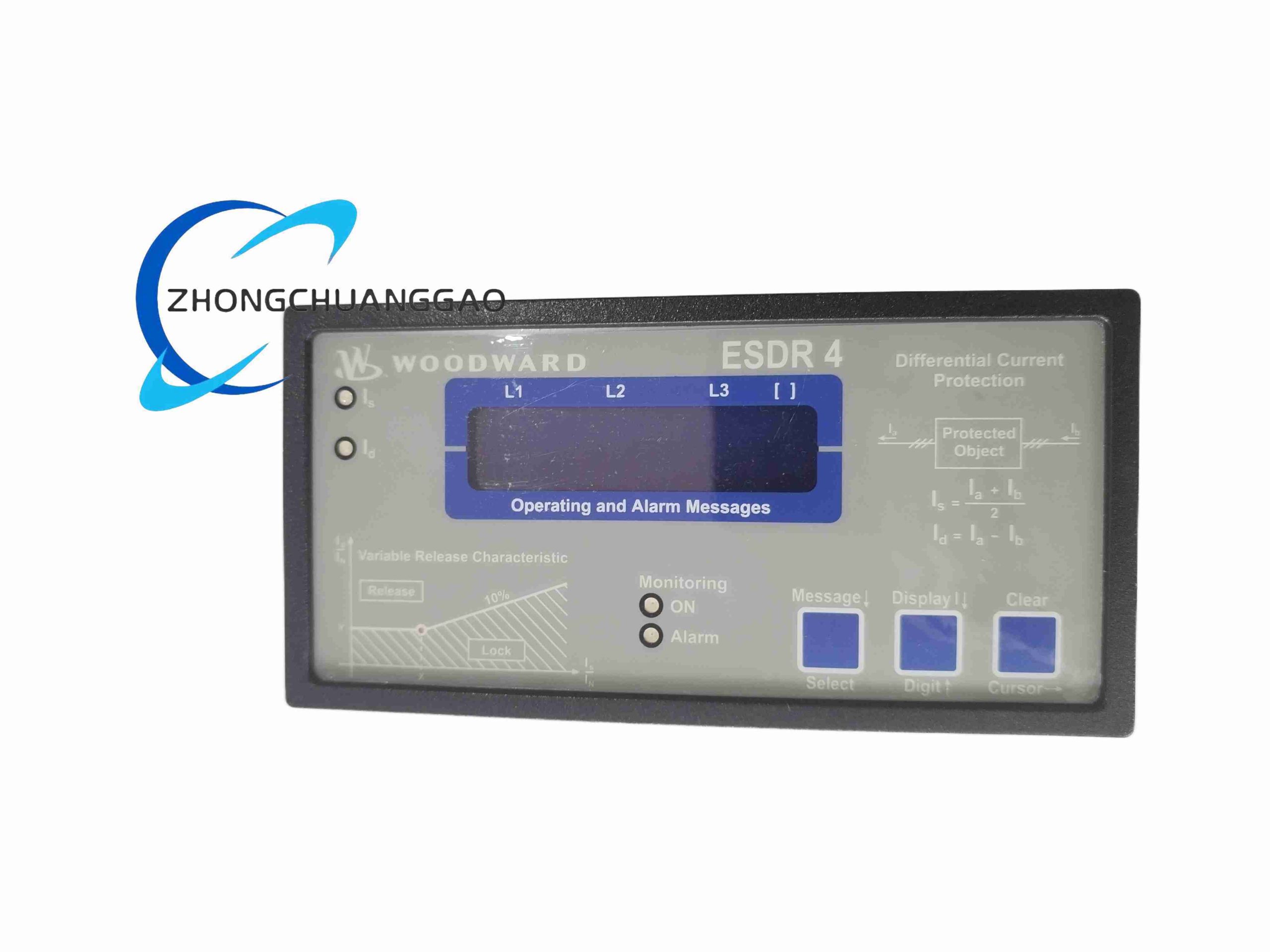
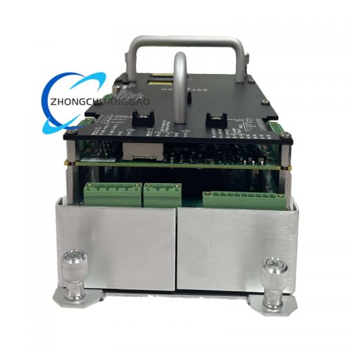
Microprocessor-based fully digital differential protection relay, dedicated to internal short-circuit and ground fault protection of synchronous generators, large transformers and medium-voltage motors. Adopts six-channel isolated CT current sampling architecture, calculates phase differential current and restraint current in real time to achieve zone-selective fault tripping without misoperation for external out-of-zone faults, widely matched with Woodward turbine governor safety control systems.
Core Technical Specifications
- Power Supply Input: 24V DC ±25% industrial control power, maximum power consumption 6 W
- CT Secondary Current Input Options: 1A or 5A user configurable
- Current Sampling Channels: 6 fully isolated CT input channels (3-phase two-side differential sampling)
- Measurement Frequency Range: 40 Hz ~ 70 Hz wide frequency adaptation
- Rated Short-Time Withstand Current (1s): 100×In (1A CT); 30×In (5A CT)
- Protection Output Relays: 4 groups of programmable trip/alarm potential-free contacts
- Display Interface: Front panel LCD digital display for real-time differential/restraint current values
- Mounting Form: Standard 1/4 DIN panel embedded installation
- Overall Dimensions: 144mm × 144mm × 78mm
- Net Weight: 0.58 kg
- Protection Grade: IP50 front panel (cabinet embedded); IP20 rear wiring terminal area
- Operating Temperature Range: -40°C ~ +70°C
Function Features
- Independent per-phase differential current calculation, built-in transformer vector group compensation algorithm to eliminate normal operation differential spurious current
- Multiple integrated auxiliary protection functions: overcurrent, undervoltage, overvoltage, over/under frequency, negative sequence current protection
- Wide adjustable differential operation threshold: 0.1A ~ 10A continuous setting range
- Front panel LCD real-time display of phase current, differential current, restraint current, fault event code
- 200 groups of fault recording data storage, record pre-fault 10 cycles and post-fault 20 cycles current waveform
- Four relay outputs separately configurable for main trip, backup trip, pre-alarm, system fault signal
- Built-in CT circuit disconnection automatic detection, CT broken wire alarm output to prevent protection misoperation
- Password parameter lock function, three-level user authority classification for protection setting management
Performance Parameters
- Fault Trip Response Time: ≤ 10 ms for internal short-circuit faults
- Current Sampling Measurement Accuracy Class: 1
- Relay Contact Rated Load Capacity: 250V AC / 8A resistive load
- CT Input Circuit Isolation Withstand Voltage: 3000V AC
- Anti-CT Saturation Algorithm: Supports 20×In saturated CT waveform correct identification
- Service Life Design Standard: 15 years continuous industrial operation
Material Composition
- Front Panel: High-temperature resistant ABS engineering plastic with scratch-resistant matte coating
- Main Circuit Board: Multi-layer noise suppression FR4 PCB, high-precision CT sampling isolation transformers
- Relay Units: Sealed electromagnetic safety relays with silver alloy anti-ablation contacts
- Wiring Terminals: Screw locking copper alloy terminals with nickel anti-oxidation plating
Structural Characteristics
- Embedded panel mounting structure, front panel fully sealed dust-proof design for industrial cabinet environments
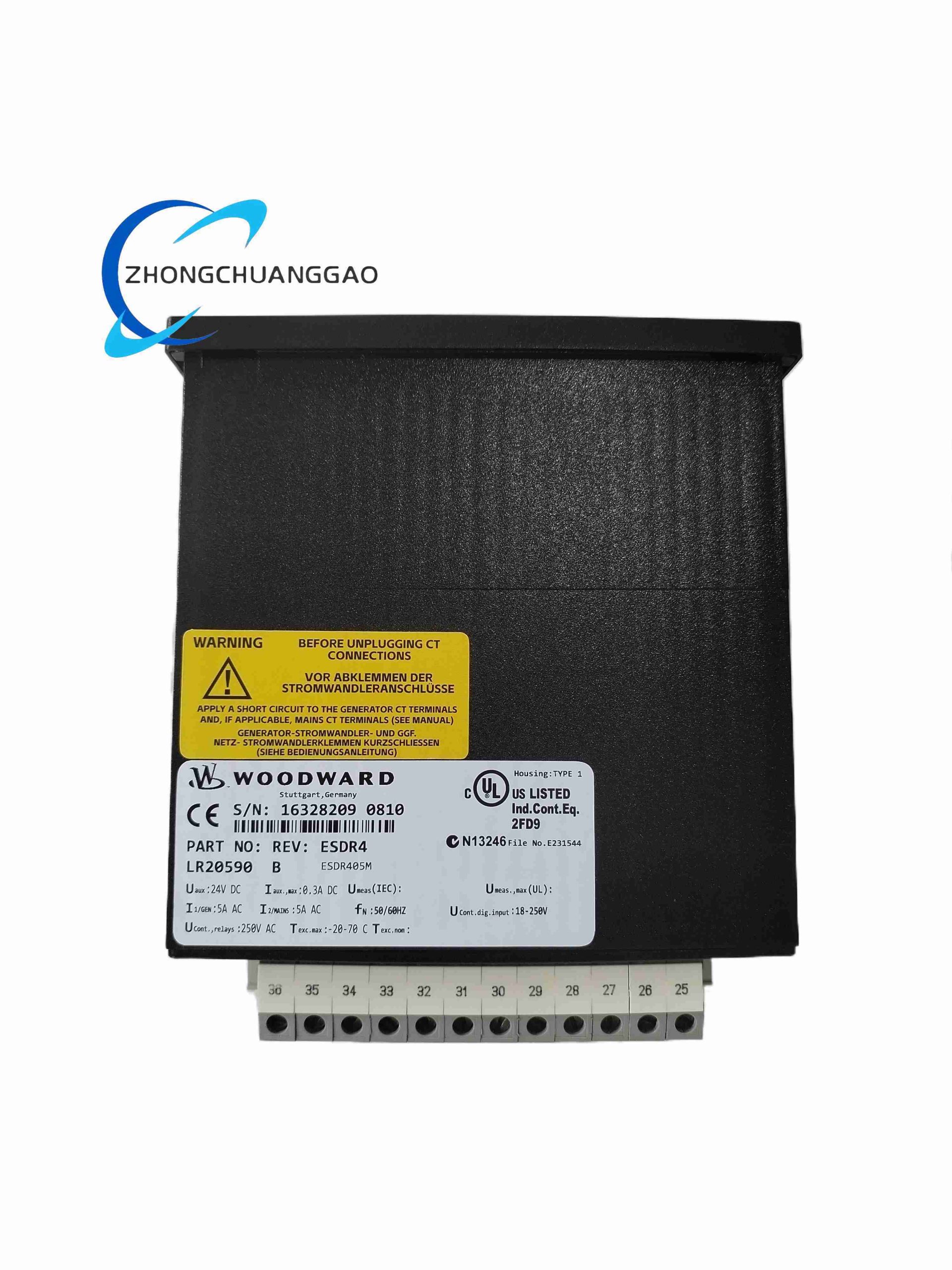
- Rear side separated wiring terminal area, CT current input terminals and power supply/output terminals partition layout
- Internal independent heat sink for power supply circuit, passive heat dissipation without cooling fan
- Front panel physical operation buttons for parameter setting, fault reset and data browsing
Working Principle
Six isolated current transformers sample current signals from two sides of protected generator/transformer equipment; analog current signals are converted to digital values via high-speed AD converter, main processor calculates per-phase differential current (Id) and restraint current (Is) based on CT ratio and vector group compensation parameters; when internal equipment short-circuit fault occurs, differential current exceeds preset operation threshold, main processor immediately drives trip relay output to cut off equipment circuit; for external out-of-zone faults, restraint current suppresses differential operation to avoid false tripping; simultaneously records fault waveform and fault code data into non-volatile flash memory for post-failure analysis.
Advantage Highlights
- Ultra-wide operating temperature range adapts to outdoor power station and thermal power plant harsh ambient conditions
- Built-in complete auxiliary protection suite, single device replaces multiple separate protection relays to reduce cabinet space
- Advanced anti-CT saturation algorithm ensures reliable protection operation under heavy short-circuit current saturation conditions
- Full fault waveform recording function provides complete data support for power system fault analysis
- Seamless communication matching with Woodward governor and turbine safety control system for integrated power plant protection
Applicable Industries
Thermal power generating units, hydropower generator sets, wind farm step-up transformers, petrochemical medium-voltage motor equipment, industrial self-owned power plant transformers, gas turbine generator protection systems
Installation Requirements
- Standard 1/4 DIN panel embedded installation, panel opening size strictly 138mm × 138mm
- CT secondary wiring must use 2.5mm² shielded copper cable, CT circuit strictly prohibited from opening circuit operation
- Power supply wiring uses separate cable from CT signal wiring, wiring separation distance ≥ 100mm
- Panel installation sealing rubber ring must be fully installed to maintain front panel IP50 dust-proof performance
- Connect relay common terminal protective earth wire to cabinet ground busbar
Usage Precautions
- Strictly forbid disconnecting CT secondary wiring when equipment is live, will generate dangerous high induced voltage
- Recalibrate differential threshold parameters after replacing CT equipment or modifying transformer tap gear
- Download fault recording data promptly after protection tripping to prevent data coverage by new faults
- Do not install the relay near frequency converters or large contactors to avoid electromagnetic interference misoperation
- Clean LCD panel only with dry soft cloth, corrosive liquid cleaner will damage display coating
Reviews
There are no reviews yet.