
Product Short Description
Product Brief Introduction
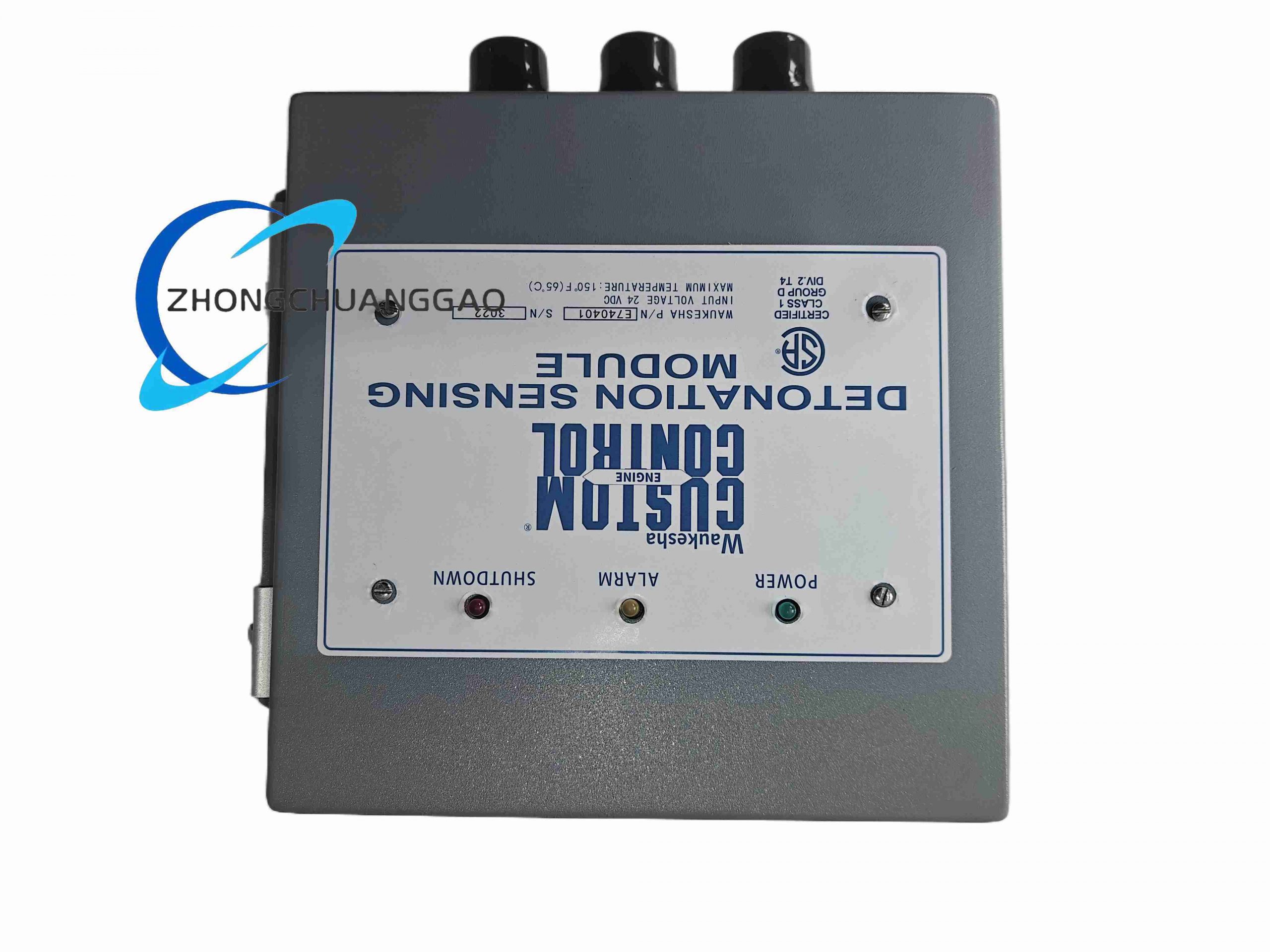
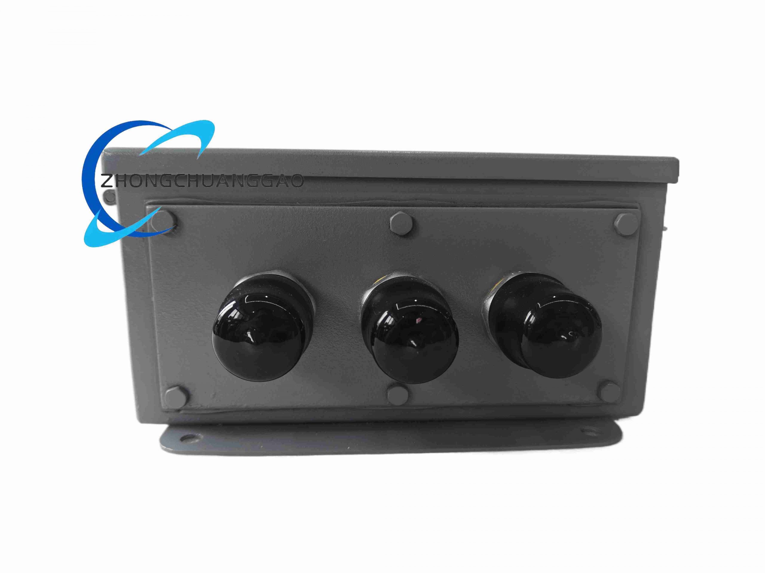
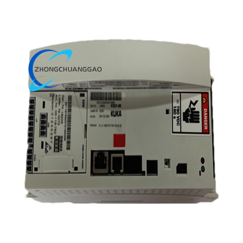
E740401 is a dedicated solid-state ignition drive control module exclusively engineered for Waukesha rich-burn / lean-burn stationary industrial gas engines, covering natural gas, landfill biogas, digester gas, and propane fuel generator sets. It serves as the core ignition signal processor that generates high-energy trigger pulses to drive engine spark plugs, synchronizes ignition timing with crankshaft position signals, and provides fault feedback to engine PLC control systems.
Description
Core Technical Specifications
- Ignition Output Electrical Parameters
- Primary Coil Drive Voltage: 24 VDC nominal input power supply, operating range 18–32 VDC
- Ignition Pulse Energy: 120 mJ high-energy capacitive discharge output per firing cycle
- Maximum Supported Engine Cylinder Count: 12 cylinder multi-cylinder gas engine timing control
- Ignition Timing Adjustment Range: 0°–40° advance crankshaft angle, programmable via external signal input
- Spark Discharge Frequency: 0–30 Hz matching engine 0–1800 RPM full operating speed range
- Overvoltage Protection Threshold: 36 VDC instantaneous surge cut-off protection
- Crankshaft Signal Input Parameters
- Compatible Sensor Types: Magnetic variable reluctance crank position pickup sensor
- Input Frequency Band: 0.5 Hz–30 kHz speed pulse signal
- Input Signal Amplitude Acceptance: 50 mV–12 VAC peak-to-peak sine wave
- Signal Isolation: 2500 Vrms optical isolation between sensor input circuit and ignition power circuit
- Environmental & Mechanical Performance Parameters
- Continuous Operating Ambient Temperature: -40°C ~ +75°C
- Storage Temperature Range: -50°C ~ +85°C
- Relative Humidity: 0–98% RH non-condensing
- Vibration Resistance Standard: IEC 60068-2-6, 10–2000 Hz, 8 g continuous vibration resistance
- Shock Resistance: 50 g peak impact for 11 ms pulse duration
- Protection Grade: IP54 sealed module housing against engine compartment dust, oil mist and light water splash
- Overall Physical Dimensions: 215 mm × 142 mm × 68 mm
- Net Weight: 1.46 kg
Function Features
Working Principle
Magnetic crankshaft position sensor transmits real-time rotational pulse signals corresponding to engine crank angle into the module’s signal conditioning circuit. An internal high-speed 32-bit microcontroller calculates real-time engine RPM and piston top dead center position, then outputs precisely timed capacitive discharge trigger signals to each ignition coil. The built-in programmable timing algorithm dynamically adjusts ignition advance angle according to engine speed and load analog input signals to optimize gas combustion efficiency. Integrated multi-channel fault detection circuit monitors coil open circuit, short circuit, sensor signal loss and over-temperature conditions, locking ignition output and transmitting digital fault codes to the engine master control system upon failure.
- Capacitive discharge ignition topology delivers consistent high spark energy under low supply voltage conditions, maintaining stable combustion for low-quality biogas fuels with variable methane content
- Built-in 0–5 VDC analog input port to receive engine manifold pressure load signal for automatic load-based ignition timing compensation
- Four independent LED status indicators: Power OK, Crank Signal Lock, Ignition Active, System Fault
- Non-volatile flash memory stores user-customized ignition timing curves and historical fault logs, retaining data for over 10 years without power supply
- Two-wire RS485 Modbus RTU communication interface for remote parameter modification, real-time engine speed reading and fault code upload
- Hardware thermal cut-off circuit: automatically disables all ignition outputs when internal circuit temperature exceeds 85°C to prevent permanent component burnout
- Reverse polarity protection on main 24 VDC power input terminal to eliminate damage from reversed wiring during field maintenance
- Multi-stage EMC filtering circuit to suppress electromagnetic interference generated by engine inverters, starters and high-current alternators
Material Composition
- Outer Enclosure: Die-cast aluminum alloy housing with black anti-corrosion powder coating, integrated internal cooling fins
- Main Circuit Substrate: Double-sided thick copper FR4 industrial PCB with full conformal polyurethane insulation coating to resist engine oil mist and condensation
- Ignition Drive Power Components: High-voltage industrial IGBT power switching transistors with aluminum bonded heat sinks
- Signal Isolation Devices: High-speed wide-temperature optocoupler chips with low temperature drift performance
- Wiring Terminal Block: Nickel-plated brass spring clamp terminals with anti-loose locking mechanism
- Internal Energy Storage Capacitors: High-temperature grade electrolytic capacitors rated for 10,000-hour continuous operation at 70°C
- Sealing Components: Fluorosilicone rubber gaskets resistant to engine oil, gasoline vapor and industrial solvent fumes
Structural Characteristics
- Horizontal flat rectangular module layout designed for wall mounting inside engine control cabinet or direct mounting on engine frame bracket
- Four symmetric M8 threaded mounting holes at housing corners for rigid bracket installation
- Front panel separated functional wiring zones clearly partitioned by molded plastic isolation barriers: power input terminals, crank sensor signal terminals, ignition coil output terminals, Modbus communication terminals
- Independent sealed internal cavity for high-voltage ignition circuit, physically separated from low-voltage signal processing circuit to eliminate high-voltage crosstalk interference
- Integrated passive cooling fin structure on aluminum housing surface to dissipate heat generated by ignition power switching components without cooling fans
- Removable transparent polycarbonate protective cover over front LED indicator window to avoid oil contamination and accidental physical damage during engine maintenance
- Internal vibration damping silicone pads fixed under PCB board to reduce mechanical stress from engine running vibration
Application Scenarios
- Landfill biogas / sewage digester gas stationary generator engine ignition control
- Natural gas distributed power station Waukesha series industrial gas gensets
- Agricultural manure biogas combined heat and power (CHP) units
- Industrial waste gas recovery gas engine power generation systems
- Remote oilfield well-site propane and associated natural gas generator sets
- Municipal wastewater treatment plant biogas power generation equipment
Installation Requirements
- Mount the module on a rigid metal bracket fixed to the engine cabinet frame; avoid mounting directly on engine cylinder block to reduce continuous vibration transmission
- Maintain minimum 25 mm clearance on all sides of the module housing for natural convection heat dissipation; do not install inside fully sealed unventilated enclosures
- Separate high-voltage ignition coil output wiring from low-voltage sensor and communication wiring with a minimum 30 cm distance; route each cable bundle in independent shielding cable trays
- Main 24 VDC power supply cable minimum cross-section 1.5 mm² stranded copper wire, terminal tightening torque controlled at 1.0 Nm
- Connect module ground terminal to engine chassis dedicated equipotential grounding busbar with 4 mm² copper braid wire to eliminate ground loop voltage interference
- Ambient installation position must avoid direct contact with engine exhaust high-temperature components; install heat insulation baffle if mounting within 50 cm of exhaust manifolds
- Magnetic crankshaft sensor signal cable must use shielded twisted pair cable, shield layer single-point grounding only at the E740401 module terminal side
Operation & Maintenance Precautions
- Cut off the 24 VDC main power supply completely before disassembling wiring terminals; high residual voltage inside ignition energy storage capacitors may cause electric shock hazards
- Do not operate the module with open-circuited ignition coil outputs; unloaded high voltage pulses will damage internal IGBT drive chips instantly
- Clean aluminum housing cooling fins every 3 months in biogas plant environments prone to dust and oil mist accumulation; blocked heat dissipation will trigger over-temperature fault shutdown
- All timing curve parameter modifications must be recorded and archived in equipment maintenance files; improper ignition advance settings will cause engine knocking, overheating or power reduction
- If fault LED illuminates continuously, sequentially inspect crankshaft sensor clearance, signal cable integrity, ignition coil insulation resistance and power supply voltage stability
- Avoid spraying high-pressure cleaning water directly onto the module housing during engine washing; even IP54 sealing cannot withstand sustained high-pressure water jet impact
- After long-term idle storage exceeding 12 months, perform full functional test with simulated crank signal before reconnecting to live engine equipment
- Do not replace internal circuit components with non-OEM equivalent parts; uncertified substitute components will degrade ignition energy output and invalidate equipment safety warranty
Reviews
There are no reviews yet.